DN-6856 • 03/08/04 — Page 5 of 9
The ONYX™ Series provides integrated solutions for any fire safety application.
6856fam1.jpg
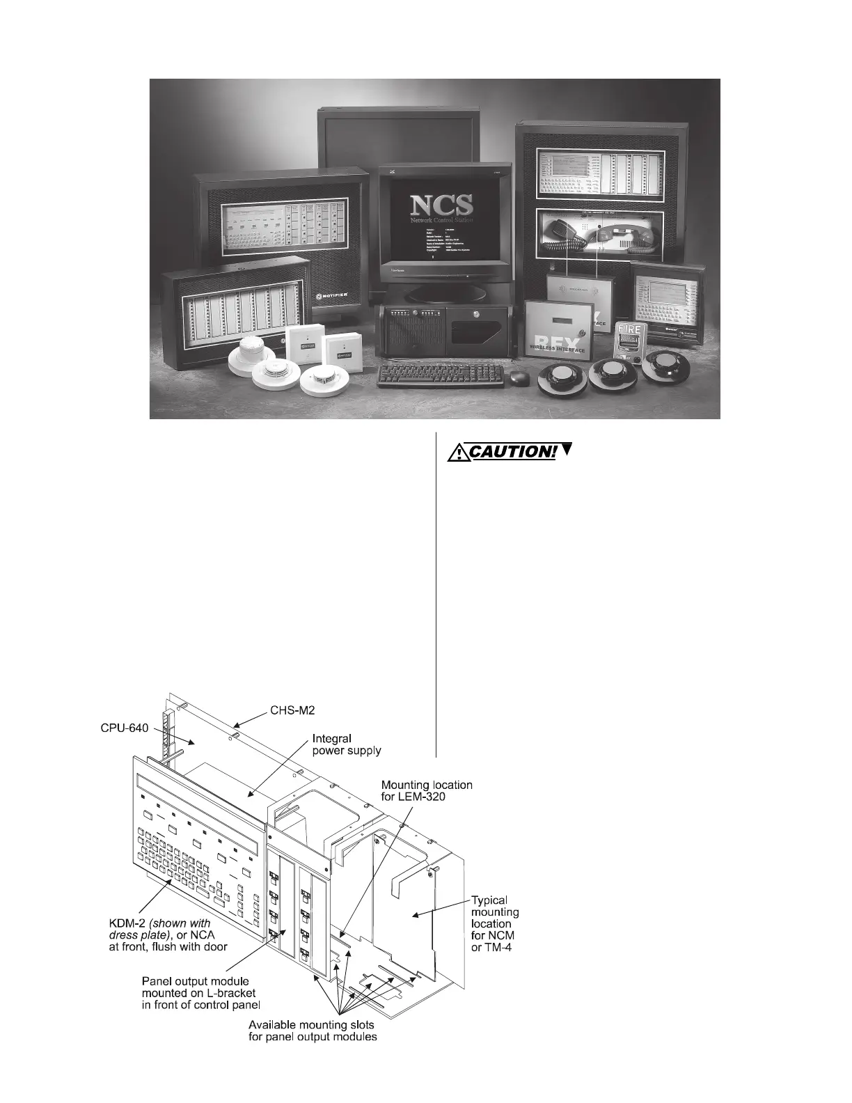
Placement of Equipment
in Chassis and Cabinet
The following guidelines outline the NFS-640’s flexible sys-
tem design.
Rows: The first row of equipment in the cabinet mounts in
chassis CHS-M2. Mount the second, third, or fourth rows of
equipment in chassis CHS-4MB (see NFS-640 Installation
Manual regarding panel output modules) or CHS-4L (for voice
components, see Voice Alarm System Manual).
Wiring: When designing the cabinet layout, consider sepa-
ration of power-limited and non-power-limited wiring as dis-
cussed in the NFS-640 Installation Manual.
Positions: A chassis offers four basic side-by-side posi-
tions for components; the number of modules that can be
mounted in each position depends on the chassis model and
the size of the individual module. There are a variety of stand-
offs and hardware items available for different combinations
and configurations of components.
It is critical that all mounting holes of the NFS-640 are
secured with a screw or standoff to ensure continuity of
Earth Ground.
Layers: The CHS-M2 accepts four layers of equipment,
including the control panel. The CPU-640 fills three positions
(left to right) in the first-installed layer (the back of the chas-
sis); its integral power supply occupies (the left) two posi-
tions in the next two layers; the optional display occupies
(the left) two positions at the front, flush with the door. Panel
output modules can be mounted in several layers with stand-
offs or an L-bracket as required. Some equipment, such as
the NCA, may be door-mounted directly in front of the control
panel. The NCA mounts onto the DP-DISP or ADP-4B. The
NCA can be used as a primary display for the NFS-640 by
directly connecting their network ports (required in Canadian
stand-alone applications).
Expansion: Installing an LEM-320 Loop Expander Mod-
ule adds a second SLC loop to the control panel. The LEM-
320 is mounted onto the CPU-640, occupying the middle-
right, second (back) slot on the chassis. If networking two or
more control panels, each unit requires a NCM-W (wire) or
NCM-F (fiber) Network Control Module. The
NCM-W/-F can be installed in any panel out-
put module position (see manual); the default
position is at the back of the chassis next to
the control panel. Option boards can be
mounted in front of the LEM-320 or NCM mod-
ules; for ease of access, complete installation
of those devices before mounting another
layer.
6856chss.wmf

 Loading...


