READ AND SAVE
THESE INSTRUCTIONS
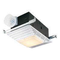
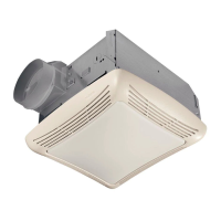
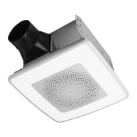
MODEL 655 / 659
HEATER/FAN/LIGHT
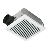
MODEL 657 FAN/LIGHT
655F, 657F AND 659F FINISH PACKS FOR USE WITH 654H HOUSING PACKS
IMPORTANT INSTRUCTIONS
READ ALL INSTRUCTIONS BEFORE INSTALLING OR
USING THIS HEATER.
To reduce the risk of fire, electric shock, or injury to persons, observe the following:
1. Use this unit only in the manner intended by the manufacturer. If you have
questions, contact the manufacturer at the address or telephone number listed in
the warranty.
2. Before servicing or cleaning unit, switch power off at service panel and lock the
service disconnecting means to prevent power from being switched on accidentally.
When the service disconnecting means cannot be locked, securely fasten a
prominent warning device, such as a tag, to the service panel.
3. Installation work and electrical wiring must be done by a qualified person(s)
in accordance with all applicable codes and standards, including fire-rated
construction codes and standards.
4. When cutting or drilling into wall or ceiling, do not damage electrical wiring and
other hidden utilities.
5. This heater is hot when in use. To avoid burns, do not let bare skin touch hot
surfaces. Keep combustible materials, such as furniture, pillows, bedding, papers,
clothes, etc. and curtains at least 3 feet (0.9 m) from the front of the heater.
6. Extreme caution is necessary when any heater is used by or near children or invalids
and whenever the heater is left operating and unattended.
7. Do not operate any heater after it malfunctions. Disconnect power at service panel
and have heater inspected by a reputable electrician before reusing.
8. Do not use outdoors.
9. To disconnect heater, turn controls to off, and turn off power to heater circuit at main
disconnect panel (or operate internal disconnect switch, if provided).
10. Do not insert or allow foreign objects to enter any ventilation or exhaust opening, as
this may cause an electric shock or fire, or damage the heater.
11. To prevent a possible fire, do not block air intakes or exhaust in any manner.
12. A heater has hot and arcing or sparking parts inside. Do not use it in areas where
gasoline, paint, or flammable vapors or liquids are used or stored.
13. Use this heater only as described in this manual. Any other use not recommended
by the manufacturer may cause fire, electric shock, or injury to persons.
14. This product must be grounded.
Models 655, 659 & 659F Heater/Fan/Lights ONLY (Nos. 15 through 20):
15. Do not install heater in a tub or shower enclosure.
16. This product is designed for ceiling installation only. This product is designed for
installation in ceilings up to a12/12 pitch. Ductwork must point up. DO NOT MOUNT
THIS PRODUCT IN A WALL.
17. Install heater at least 6 inches from floor or any adjacent wall.
18. Do not connect heater to dimmer switch or speed control.
19. Provide a separate 15 AMP circuit. Use 14 GA. power cable of type which meets
code. (Separate 20 AMP circuit and 12 GA. wire for Model 655.)
20. For greatest efficiency, install heater so heat is directed toward tub or shower area.
Avoid directing toward walls or windows.
Models 657 & 657F Fan/Lights ONLY (No. 21):
21. Acceptable for use over a bathtub or shower when installed in a GFCI protected
branch circuit.
SAVE THESE INSTRUCTIONS
PREPARATION
STEPS 1 THRU 3 - MODELS 655, 659 & 659F ONLY
1. Make sure the heater assembly is unplugged from the RED receptacle.
2. Loosen the two retaining screws on the inside of the heater discharge
opening. Place a screwdriver tip between the outer wall of the discharge
opening and the fan housing. Gently pry outward until the exhaust
discharge slips off the support lip on the outer housing. (FIG. 1)
3. Unhook hinge pins and lift heater assembly out of housing. (FIG. 2)
CAUTION: Remove the shipping ring from the heater blower inlet before
operating the heater.
4. Unplug the fan assembly from the BLACK receptacle. Remove the plastic
bag and set it aside.
5. Remove the mounting screw and carefully lift the fan assembly out of
the housing. (FIG. 3)
6. Refer to the wiring diagram of your unit on the next page. Remove
appropriate knockout(s) by inserting a screwdriver blade into slots and
bending it back and forth to break tabs. (FIG. 4)
7. Insert the adjustable mounting brackets into the bracket channels on the
housing. (FIG. 5)
FIG. 1
FIG. 2
FIG. 3
FIG. 4
FIG. 5
KNOCKOUTS
RETAINING
SCREWS
HINGE PIN