CLASSIFICATION
The product is a Class II device (enhanced insulation) and must be connected to
the following leads:
Phase L1 (L) 120 V, Phase L2 (N) 0/120 V, Max. load 15 A (resistive load)
The terminals are suitable for eld wiring cables of 12 to 22 AWG.
Heating element in accordance with the supply voltage.
TECHNICAL DATA
Supply ...............................................................................120/240 Vac 50/60 Hz
Load ..................................................................................max. 15 A (resistive load)
Power ...............................................................................1800 W at 120 Vac
...........................................................................................3120 W at 208 Vac
...........................................................................................3600 W at 240 Vac
GFCI ..................................................................................Class A (5 mA trip level)
Temperature range ...........................................................+5 to +40°C, +41 to +104°F
Amb. temp. range .............................................................0 to +25°C, +32 to +77°F
Construction of Control: Electronic room thermostat for regulating electrical
underoor heating.
Method of Mounting Control: Independently mounted control for ush mounting
Type of Action: ..................................................................Type 2.B.
Rated Impulse Voltage : ....................................................2500 V
Control Pollution Degree: .................................................PD2
CERTIFICATION UL Listed for the US and Canada
According to the following standards:
Thermostat: UL 60730-1
UL 60730-2-9
CSA E60730-1:13
CSA E60730-2-9
UL le number: E157297
GFCI: UL 943 4
th
ed.
CSA C22.2 No. 144.1-06
Patent pending
CLASSIFICATION
Le produit est un dispositif de classe II (isolation améliorée) et doit être branché
aux broches suivantes :
Phase L1 (L) 120 V, Phase L2 (N) 0/120 V, Charge max. 15 A (charge résistive)
Les bornes sont appropriées aux ls de câblage de 12 à 22 AWG.
L’élément chauffant est conforme à la tension d’alimentation.
FICHE TECHNIQUE
Alimentation .....................................................................120/240 Vac 50/60 Hz
Charge ..............................................................................max. 15 A (charge
résistive)
Puissance .........................................................................1800 W à 120 Vac
...........................................................................................3120 W à 208 Vac
...........................................................................................3600 W à 240 Vac
GFCI ..................................................................................Classe A (seuil de
déclenchement 5 mA)Plage de température ...................+5 à +40 °C, +41 à +104 °F
Plage de temp. amb. ........................................................0 à +25 °C, +32 à +77 °F
Construction du dispositif de commande : Thermostat électronique de pièce pour
réguler un plancher chauffant électrique.
Méthode de montage du dispositif : Dispositif de commande à montage
indépendant pour montage encastré
Action de type : .................................................................Type 2.B.
Tension assignée de choc : ..............................................2500 V
Milieu de pollution du dispositif de commande : .............DP2
CERTIFICATION : Homologué UL au Canada et aux États-Unis
Selon les normes suivantes :
Thermostat : UL 60730-1
UL 60730-2-9
CSA E60730-1:13
CSA E60730-2-9
Numéro de dossier UL : EE157297
GFCI : UL 943 4
e
éd.
CSA C22.2 No. 144.1-06
Brevet en instance
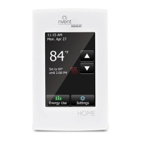
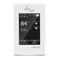
ITEMS/ AFFICHAGES
Change date and time
Pour changer la date et l’heure
Current temperature
Température courante
Target temperature or setpoint
Température visée/point de contrôle
Heating indicator - when visible,
system is heating.
Indicateur de chauffage - si visible, le
chauffage est activé
Access energy use data
Données d’utilisation énergétique
Access Main Menu
Pour accéder au menu principal
GFCI test Button
Bouton de test GFCI
GFCI Indicator
Indicateur GFCI
On/Off Button
Press to turn system ON/Reset GFCI
Hold to turn system OFF
Bouton MARCHE/ARRÊT
Appuyer pour activer système/Réarmer GFCI
Mainenir appuyé pour désactiver système
3
4
5
6
7
8
9
HOME SCREEN/ÉCRAN D’ACCUEIL
For detailed information regarding nVent NUHEAT thermostat warranty, please visit nVent.com/NUHEAT/Pour plus de détails sur la garantie du thermostat NUHEAT, consulter nVent.com/NUHEAT.
nVent NUHEAT Home Quick Start Guide
Guide De Démarrage Rapide - NUHEAT Home
WARNINGS:
To avoid electric shock, disconnect the heating system power supply at the
main panel before installation and maintenance of the thermostat. Keep
thermostat air vents clean and free from obstruction. This thermostat is an
electrical product and must be installed in compliance with the National
and/or Local Electrical Code. Installation must be performed by qualied
personnel where required by law.
AVERTISSEMENTS :
Pour éviter une décharge électrique, coupez l’alimentation du système de
chauffage au panneau de distribution avant l’installation et/ou l’entretien du
thermostat. Gardez toujours les évents du thermostat propres pour éviter
les obstructions. Ce thermostat est un produit électrique et doit être installé
conformément aux codes nationaux et locaux de l’électricité. Lorsque la loi
l’exige, le thermostat doit être installé par du personnel qualié.
nVent.com
©2018 nVent. All nVent marks and logos are owned or licensed by nVent Services GmbH or its affiliates. All other
trademarks are the property of their respective owners. nVent reserves the right to change specifications without notice.
Nuheat-IM-H59313-HomeThermostatProg-EN-1805
NORTH AMERICA AMÉRIQUE DU NORD
Tel. Numéro sans frais +1.800.545.6258
Fax Télécopieur +1.800.527.5703
thermal.info@nvent.com
HOME