3G3AX-MX2-ECT
EtherCAT
®
Communication Unit
(For MX2 series)
INSTRUCTION MANUAL
Thank you for purchasing this OMRON product.
Please read this instruction sheet and thoroughly familiarize yourself
with the functions and characterisitcs of the product before use.
Please retain this sheet for future reference
OMRON Corporation
©OMRON Corporation 2010 All Rights Reserved.
2114114-8*
Inverter
Model
3G3MX2-
Manufacturer
OMRON
Series
MX2 series
Specifications
Power supply
Application environment
Operating temperature
Humidity
Storage temperature
Weight
Supplied from Inverter
Indoors (with no corrosive gas, oil mist,
metal powder, etc.)
-10 to 50 °C
20 to 90 % (with no condensation)
-20 to 65 °C
100 g max.
ŶIndications and Meanings of Safety Information
Safety Precautions
The Inverter has high voltage parts inside which,
if short-circuited, might cause damage to itself or other property.
Place covers on the openings or take other precautions to make
sure that no metal objects such as cutting bits or lead wire scraps
go inside when installing and wiring.
Do not dismantle, repair or modify the product.
Doing so may result in an injury.
Do not remove the terminal cover or remove/install the
Communication Option Unit while power is being supplied or
within 10 minutes after turning the power off.
Doing so may result in a serious injury due to an electric shock.
In this instruction sheet, the following precautions and signal
words are used to provide information to ensure the safe use of
the 3G3AX-MX2-ECT EtherCAT Communication Unit.
The information provided here is vital to safety.
Strictly observe the precautions provided.
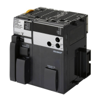
ŶAppearance and Names of Parts
ŶMeanings of Signal Words
WARNING
Indicates a potentially hazardous situation which,
if not avoided, may result in minor or moderate
injury or in property damage.
CAUTION
Indicates a potentially hazardous situation which,
if not avoided, will result in minor or moderate injury,
or may result in serious injury or death. Additionally
there may be significant property damage.
ŶAlert Symbols in this Document
WARNING
CAUTION
Precautions for Safe Use
ŶInstallation and Storage
Do not store or use the product in the following places.
Locations subject to direct sunlight.
Locations subject to ambient temperature exceeding the specifications.
Locations subject to relative humidity exceeding the specifications.
Locations subject to condensation due to severe temperature fluctuations.
Locations subject to corrosive or flammable gases.
Locations subject to exposure to combustibles.
Locations subject to dust (especially iron dust) or salts.
Locations subject to exposure to water, oil, or chemicals.
Locations subject to shock or vibration.
ŶTransporting, Installation and Wiring
Do not drop or apply a strong impact on the product.
Doing so may result in damaged parts or malfunction.
When transporting an Inverter in which this product has been installed,
hold the radiation fins of the Inverter.
Do not remove the cover from the Communication Option Unit.
Also make sure the unit fixing screws are tightened with the specified torque.
Provide an appropriate stopping device to secure safety.
In particular, note that if you enable the setting to continue operation
in case of communication error, the Inverter will not stop when an error
occurs and equipment damage may result.
Take sufficient shielding measures when using the product in the following
locations. Not doing so may result in damage to the product.
Locations subject to static electricity or other forms of noise.
Locations subject to strong magnetic fields.
Locations close to power lines.
ŶMaintenance and Inspection
Be sure to confirm safety before conducting maintenance,
inspection or parts replacement.
ŶOperation and Adjustment
Be sure to confirm the permissible range of motors and machines before
operation because the inverter speed can be changed easily from low to high.
ŶMODBUS-RTU Communication
Once this Communication Option Unit is installed, the MODBUS-RTU
communication function of the Inverter is disabled.
Precautions for Correct Use
ŶProduct Disposal
Comply with the local ordinance and regulations when disposing of the product.
Conformance to E8 Directives
Please attach the ferrite core to each EtherCAT communications cable.
This is a Class A product. In residential areas it may cause radio
interference, in which case the user may be required to take adequate
measures to reduce interference.
Overview
EtherCAT Communication Unit (3G3AX-MX2-ECT) can be installed in
OMRON’s Inverters (MX2 series) to let you exchange various data with the
host via EtherCAT.
Installation Procedure
Remove the optional board cover from the Inverter and install the EtherCAT
Communication Unit and fix it with screws.
(For details, refer to the manual for installation.)
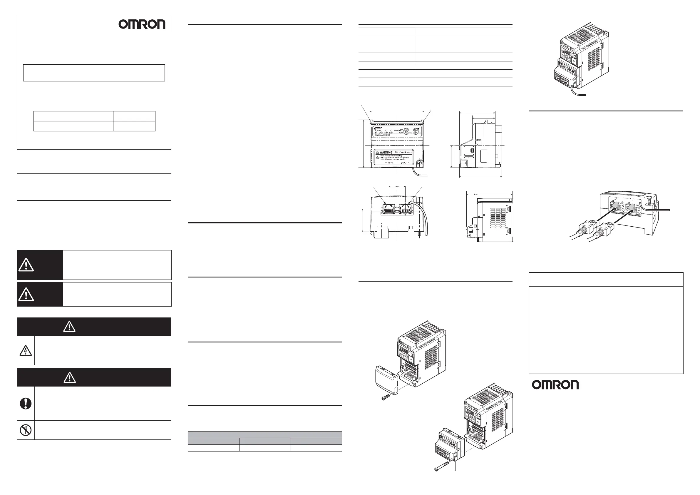
Wiring Procedure
Securely connect the EtherCAT communication cable connector to the
EtherCAT Communication Unit by inserting the connector all the way until
it clicks.
Connect the communication cable from the EtherCAT master side
to the communication connector IN of the Communication Unit.
Connect the communication connector OUT to the communication connector
IN of the next EtherCAT slave.
Do not connect the communication connector OUT of the last EtherCAT slave.
Data will not be communicated correctly if the input/output are connected
in reverse.
For communication cables, be sure to use the Category 5 straight type or
higher cables, double shielded by braid and aluminum tape.
Connent the FG cable of this unit to ground as close as possible.
Do not squeeze the FG cable into the EtherCAT Communication Unit.
ŶOMRON Corporation
Shiokoji Horikawa, Shimogyo-ku, Kyoto, 600-8530, Japan
ŶOmron Europe B.V.
Wegalaan 67-69, NL-2132 JD Hoofddorp, The Netherlands
(1) Removal
(3) Wiring
Precautions for Compliance with UL Standards
and CSA Standards
Notice to Users of the 3G3AX-MX2-ECT in the USA and Canada.
Please use the following installation infomation instead of the general
information in the instruction manuals in order to use the product under
certiffied conditions of UL and CSA when the product is installed in the USA
or Canada. These conditions are required by NFPA 70, National Electrical
Code in the USA and the Canadian Electrical Code, Part I in Canada and
may vary from information given in the product manuals or safety precautions.
Environment
Surrounding Air Temperature: 50°C
The EtherCAT Communication Unit can be built into the following Inverters.
(2) Installation
STOP
RESET
RUN
Hz
A
ALM
PRG
3
G3MX2
INVERTER
RUN
PWR
SYSDRIVE
STOP
RESET
RUN
Hz
A
ALM
PRG
3G3MX2
INVERTE
R
RUN
PWR
SYSDRIVE
STOP
RESET
RUN
Hz
A
ALM
PRG
3G3MX2
INVERTER
RUN
PWR
SYSDRIVE
*1. The dimension of the inverter with EtherCAT Communication Unit is
inverter dimension plus 26.4 mm to D-dimension as shown in the figure.
(The D- dimension of inverter changes with its capacity; refer to the
user's manual of the inverter for its dimension.)
SUITABILITY FOR USE
Omron Companies shall not be responsible for conformity with any standards,
codes or regulations which apply to the combination of the Product in the Buyer's
application or use of the Product. At Buyer's request, Omron will provide
applicable third party certification documents identifying ratings and limitations of
use which apply to the Product. This information by itself is not sufficient for a
complete determination of the suitability of the Product in combination with the
end product, machine, system, or other application or use. Buyer shall be solely
responsible for determining appropriateness of the particular Product with respect
to Buyer's application, product or system. Buyer shall take application
responsibility in all cases.
NEVER USE THE PRODUCT FOR AN APPLICATION INVOLVING SERIOUS
RISK TO LIFE OR PROPERTY WITHOUT ENSURING THAT THE SYSTEM AS
A WHOLE HAS BEEN DESIGNED TO ADDRESS THE RISKS, AND THAT THE
OMRON PRODUCT(S) IS PROPERLY RATED AND INSTALLED FOR THE
INTENDED USE WITHIN THE OVERALL EQUIPMENT OR SYSTEM.
Trademark
EtherCAT
®
is registered trademark and patented technology, licensed
by Beckhoff Automation GmbH, Germany.
10.310.3
28.2
67.6
27.9
53.1
28.6
Status indicator
Communications
connector (IN)
Communications
connector (OUT)
Rotary switches for node
address setting
FG Cable
EtherCAT master side
EtherCAT slave side
OUT
IN
OUT
IN
60.0
44.9
FG Cable
FG Cable
D
*1
26.4 mm
*1
Cat.No.
Manual Name
3G3AX-MX2-ECT User’s Manual I574-E1
20521&RUSRUDWLRQ
,QGXVWULDO$XWRPDWLRQ&RPSDQ\
7RN\R-$3$1
&RQWDFWZZZLDRPURQFRP
5HJLRQDO+HDGTXDUWHU
20521(8523(%9
:HJDODDQ-'+RRIGGRUS
7KH1HWKHUODQGV
7HO
)D[
20521$6,$3$&,),&37(/7'
1R$$OH[DQGUD5RDG
/REE\$OH[DQGUD7HFKQRSDUN
6LQJDSRUH
7HO
)D[
20521(/(&7521,&6//&
*UHHQVSRLQW3DUNZD\6XLWH
+RIIPDQ(VWDWHV,/86$
7HO
)D[
20521&+,1$&2/7'
5RRP%DQNRI&KLQD7RZHU
<LQ&KHQJ=KRQJ5RDG
3X'RQJ1HZ$UHD6KDQJKDL
&KLQD
7HO
)D[
1RWH6SHFLILFDWLRQVVXEMHFWWRFKDQJHZLWKRXWQRWLFH

 Loading...