CS/CJ Series HOST Link Driver
GP-Pro EX Device/PLC Connection Manual
31
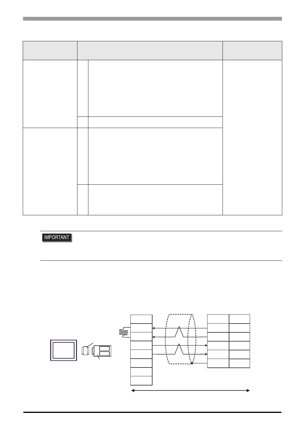
Cable Diagram 3
A) When using the COM port conversion adapter (CA3-ADPCOM-01), the connector terminal block conversion
adapter (CA3-ADPTRM-01) by Pro-face and your own cable
• 1:1 connection
Display
(Connection Port)
Cable Notes
GP
*1
(COM1)
AGP-3302 (COM2)
*1 Except AGP-3302 Series
A
COM port conversion adapter by Pro-face
CA3-ADPCOM-01
+
Connector terminal block conversion adapter
by Pro-face
CA3-ADPTRM-01
+
Your own cable
The cable length must
be 500m or less.
B Your own cable
GP
*1
(COM2)
C
Online adapter by Pro-face
CA4-ADPONL-01
+
Connector terminal block conversion adapter
by Pro-face
CA3-ADPTRM-0
+
Your own cable
D
Online adapter by Pro-face
CA4-ADPONL-01
+
Your own cable
• Please turn ON the termination resistance switch on the PLC.
• Set the 2wire/4wire toggle switch to 4wire.
• Note that pole A and pole B are reversely named for the Display and the External
Device.
Display
CA3-ADPCOM-01
CA3-ADPTRM-01
Termination
resistance
220Ω 1/4W
Terminal
block
Signal
name
Shield
External Device
D-sub 9 pin (socket)
Pin
Signal
name
Your own cable
SDB
SDA
RDB
RDA
FG
2
1
8
6
Shell
RDA
RDB
SDA
SDB
TERMRX
SG
FG
 Loading...


