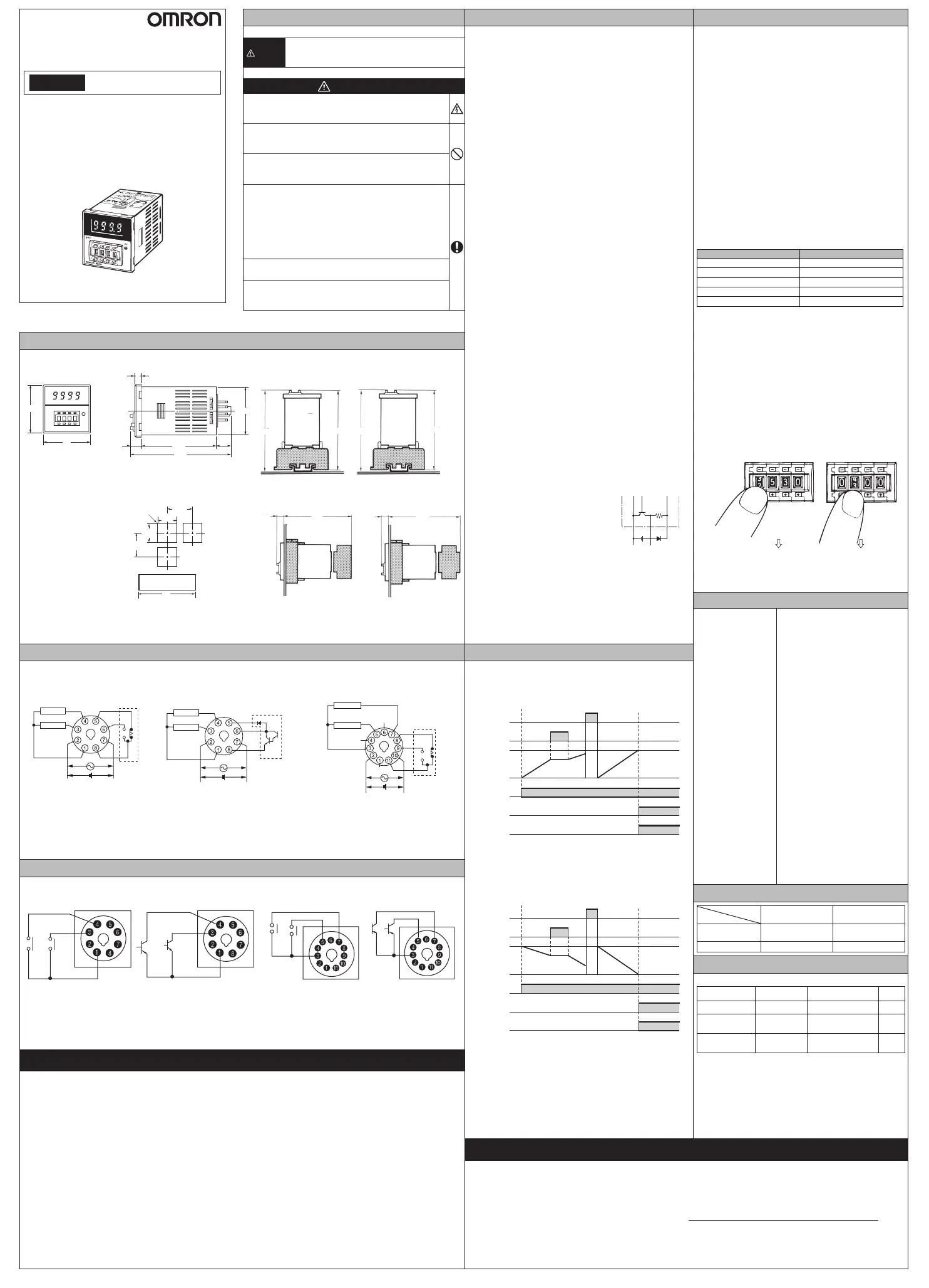
Dimensions and Installation
n DIMENSIONS
[mm]
5.27
(10.9)
14.2
97.6
6
@44.8
48
48
n PANEL CUTOUT [mm]
60 min.
Standard panel cutout is as
shown in the right gure.
(conforms to DIN43700)
Note 1. The thickness of
mounting panel
should be 1 to 5 mm.
Note 2. It is possible to
mount the products
side-by-side. The di-
mension is as shown
in the right gure.
45
㧗0.6
㧙0
㧗0.6
㧙0
45
A
A=(48n-2.5)
+1
-0
n Units mounted
side-by-side
R0.5 max.
60 min.
n INSTALLATION [mm]
Surface mounting
Model H5CN
-@@N
-X@NS
P2CF-08(-E) P2CF-11(-E)
Model H5CN
-X@NM
Flush mounting
Model H5CN
-@@N
-X@NS
+
Adapter
Model H5CN
-X@NM
+
Adapter
P3G-08
Y92F-30
P3GA-11
Y92F-30
Connection
● Model H5CN-@@N
(without memory backup)
Contact output
● Model H5CN-X@NS
(without memory backup)
Transistor output
● Model H5CN-X@NM
(with memory backup)
Contact output
Contact
output
Gate
Internal circuit
Contact
output
100 to 240 VAC
12 to 48 VDC
Reset
Gate
Internal circuit
Transistor
output
100 to 240 VAC
12 to 48 VDC
Reset
Gate
DO NOT USE
DO NOT
USE
Internal circuit
100 to 240 VAC
24 VDC
Reset
DO NOT
USE
▪ Model H5CN-@@N/X@NS: Terminal 1 is internally connected to terminal 2 if the Counter is a model that operates with DC.
Model H5CN-X@NM: Terminal 3 is internally connected to terminal 2 if the Counter is a model that operates with DC.
▪ A diode is connected between terminal 5 and 6 to absorb the counter electromotive force that occurs when connecting an
inductive load.
▪ Do not wire the terminals which are not used.
Input Connection
● Model H5CN-@@N/X@NS (without memory backup)
Gate input
Reset input
Gate input
Reset input
Connection of contact signal input Connection of transistor signal input
● Model H5CN-X@NM (with memory backup)
Connection of contact signal input
Connection of transistor signal input
Gate input
Reset input
Gate input
Reset input
Suitability for Use
OMRON Companies shall not be responsible for conformity with any standards, codes or regulations which apply to the combina-
tion of the Product in the Buyer’s application or use of the Product. At Buyer’s request, OMRON will provide applicable third party
certication documents identifying ratings and limitations of use which apply to the Product. This information by itself is not sufcient
for a complete determination of the suitability of the Product in combination with the end product, machine, system, or other ap-
plication or use. Buyer shall be solely responsible for determining appropriateness of the particular Product with respect to Buyer’s
application, product or system. Buyer shall take application responsibility in all cases.
NEVER USE THE PRODUCT FOR AN APPLICATION INVOLVING SERIOUS RISK TO LIFE OR PROPERTY OR IN LARGE
QUANTITIES WITHOUT ENSURING THAT THE SYSTEM AS A WHOLE HAS BEEN DESIGNED TO ADDRESS THE RISKS, AND
THAT THE OMRON PRODUCT(S) IS PROPERLY RATED AND INSTALLED FOR THE INTENDED USE WITHIN THE OVERALL
EQUIPMENT OR SYSTEM.
Precautions for Safety Use
Please comply strictly with the following instructions which are
intended to ensure safe operation of thecontroller
.
1)
Make sure the proper product is specied for the application
.
2) For correct use, do not subject the product to the following
conditions.
• Dramatic temperature uctuations
• High humidity or where condensation may occur
• Severe vibration and shock
• Where excessive dust, corrosive gas, or direct sunlight may
be present
3) This product is not waterproof or oil resistance. Do not use the
product in any of the places subject to splashing liquid or oil
atmosphere.
4)
Use and store the product within the rated ranges given for the
product model you are using. If necessary, use forced cooling
.
If the product is stored below −10°C, allow it to warm up for three
hours at room temperature before turning ON the power supply
.
5) Do not cover the vent holeson the products and the area
around the product in order to ensure thermal dissipation.
6) Wiring all terminals correctly.
7) Do not wire the terminals which are not used.
8)
Use specied size crimped terminals (M3.5, thickness 7.2 mm
max.) for wiring with a gage of AWG 24 to AWG 18 (equal to a
cross section area of 0.205 to 0.823 mm
2
).
(The wiring stripping length is 5 to 6 mm.)
Up to two wires of same size and type, or two crimped termi-
nals can be inserted into a single terminal.
9) Use this product within the rated power supply voltage and
control output.
10)
Use a switch, relay, or other contact to turn the power supply
ON instantaneously. If the voltage is applied gradually, the
power may not be reset or output malfunctions may occur
.
11) Do not apply the supply voltage directly from external to
transistor output.
12) Install and clearly label a switch or circuit breaker so that the
operator can quickly turn OFF the power supply.
13) Install the input signal resource and the product itself apart
from noise generating sources and wiring which is carrying
the high power current to cause noise.
14) Separate the product from any sources of excessive static
electricity, such as forming materials and pipes carrying
powder and liquid materials.
15) Interlock the power to the product with a relay so that the
product will not be left in an output on condition for long peri-
ods. Leaving the product in an output-on condition for a month
or longer, especially in places with high temperatures, may
result in deterioration to internal parts, such as an electrolytic
capacitor.
16)
Internal circuit voltage (5 V) is output to the no-voltage input
terminals, which may cause some connected devices to
malfunction or fail. Check the specications of the input device
(e.g., rated output voltage or whether a power supply circuit
diode is built in)
.
To prevent power supply devices from
being subjected to charging accidents,
connect a diode as in the gure when
using a power supply voltage of 5 V or
less to operate input devices that do
not have a diode built into the power
supply circuit.
17) The exterior of the product may be damaged by organic sol-
vents (such as thinners or benzene), strong alkali, or strong
acids.
18)
Check that the LED indicators are operating normally. Depending
on the operating environment, the indicators and plastic parts may
deteriorate faster than expected, causing the indicators to fail.
Periodically perform inspections and replacements
.
19) Use tools when separating parts for disposal.
20) When disposing of the product, observer all local ordinances
as they apply.
Sensor
Input
Model H5CN
DIGITAL TIMER
English INSTRUCTION MANUAL
Thank you for purchasing this OMRON product.
This manual primarily describes the functions, performance and
application methods needed for optimum use of the product.
Please observe the following items when using the product.
▪ This product is designed for use by qualied personnel with a
knowledge of electrical systems.
▪ Before using the product, thoroughly read and understand this
manual to ensure correct use.
▪ Keep this manual in a safe location so that it is available for
reference whenever required.
OMRON Corporation
©All Rights Reserved
2288978-2A (Side-B)
Safety Precautions
l Key to WARNING Symbols
CAUTION
Indicates a potentially hazardous situation which, if
not avoided, is likely to result in minor or moderate
injury or property damage.
l Warning Symbols
CAUTION
Do not touch the terminals while power is being supplied.
Doing so many occasionally result in minor injury due to
electric shock.
Do not use the product where subject to ammable or
explosive gas.
Otherwise, minor injury from explosion may occasionally occur
.
Never disassemble, modify or repair the product or touch
any of the internal parts. Minor electric shock, re, or
malfunction may occasionally occur.
The life expectancy of output relays varies considerably
with the output load and switching conditions. Always con-
sider the application conditions and use the output relays
within their rated load and electrical life expectancy. If the
output relays are used past their life expectancy, contact
fusing or burning may occasionally occur. Also, never
exceed the rated load current. When using a heater, surely
use a thermo switch in the load circuit.
Tighten the terminal screws to between 0.74 and 0.90 N·m.
Loose screws may occasionally result in re.
Do not allow pieces of metal, wire clippings, or ne metallic
shavings or lings from installation to enter the product. Doing
so may occasionally result in electric shock, re, or malfunction
.
Set the reset time at lease 0.5 sec during power recovery (power reset).
Timing Chart (Power ON Delay)
● Digital display
UP Display
Reset input
Time up
indication
Control output
Power supply
Digital display
Setting value
Gate input
Power ON
Time UP
no digital
display
DOWN Display
Reset input
Time up
indication
Control output
Power supply
Digital display
Setting value
Gate input
Power ON
Time UP
no digital
display
Contact Address
OMRON EUROPE B.V.
Wegalaan 67-69, NL-2132 JD Hoofddorp The Netherlands
Phone 31-2356-81-300
FAX 31-2356-81-388
OMRON ELECTRONICS LLC
One Commerce Drive Schaumburg, IL 60173-5302 U.S.A
Phone 1-847-843-7900
FAX 1-847-843-7787
OMRON ASIA PACIFIC PTE. LTD.
No. 438A Alexandra Road # 05-05/08(Lobby 2),
Alexandra Technopark, Singapore 119967
Phone 65-6835-3011
FAX 65-6835-2711
OMRON Corporation
Shiokoji Horikawa, Shimogyo-ku, Kyoto 600-8530 JAPAN
Precautions for Correct Use
1) Inrush current will be carried when turning on the power.
If the capacity of the power for the product is insufcient,
the product cannot start. Use a power supply, breakers,
contacts which sufcient capacity.
100 to 240 VAC specications
Approx. 0.8 A for 264 VAC
12 to 48 VDC specications Approx. 0.4 A for 52.8 VDC
2)
Since 50 ms after the power is turned ON is required as the raise
time of the internal circuit voltage, note that the product may not
operate in response to any input signal during this period
.
3) Since100 ms after the power is turned OFF (or momen-
tary power failures) is required as the fall time of the
internal circuit voltage, note that the product may respond
to input signals during this period
.
4) The product memorizes the status just before occurring
the electric failure memory with non-volatile memory. The
rewriting lifespan of the non-volatile memory is 1,000,000
or more. The non-volatile memory rewrites the setting
condition into the initial setting one when the power OFF
and reset input. (-M type only)
5)
Model H5CN 12-48 VDC specication use transformer-less
power supply which the power terminals and input terminals are
not insulated. When use this specication, the internal parts of
the product may be occasionally burnt (damaged) if the wiring
is not correct. Pay attention to check the wiring before use
.
6) Operation time setting
Time setting range
Setting range Model
0.001 sec~9.999 sec
H5CN-@Z@
0.01 sec-99.99 sec
H5CN-@A@
0.1 sec-999.9 sec
H5CN-@B@
1 sec-99min59 sec
H5CN-@C@
1 min-99h59 min
H5CN-@D@
▪
The H5CN Timer is capable of reading the input data at any time dur-
ing normal operation. This means that the set time can be changed
during power application. This feature sets back the output from the
timer by temporarily setting the longer time or quickens the output by
setting the shorter time. During normal operation, the set time may
be accidentally changed by touching a thumbwheel switch, causing
the timer to operate with a different set time. To prevent this possibil-
ity, use the optional Y92A-48B Protective Cover.
▪
When the set time is all zeroes (e.g., 000.0 s or 00 h 00 min), there will
be a momentary control output upon power application, which can be
used to check normal output. When changing the set time during nor-
mal operation, pay attention not to alter the set value to this all zeroes
.
▪
When changing the set time while power is being supplied, an inade-
quate push of the thumbwheel switches willdisplay two numbers in one
display window, causing the operating count to drift widely. Therefore,
press the thumbwheel switches surely. Take particular care when the
other three digits are all zeroes, because the improper setting of the
fourth switch to create four zeroes will cause an instantaneous output
.
(Undesirable
changes in
the settings)
(Conceivable
operating time)
00 h 00 min
(instant output)
5 min 30 s
min minhourssec
▪ Take particular care with the H5CN-@Z@, which is capable
of setting in 1/1000th of a second because there is an error
of between 0.03 to 0.05 s. (Repeat accuracy is 1 to 2 ms)
Specications
Power supply voltage 100 to 240 VAC 50/60 Hz
12 to 48 VDC, 24 VDC
(20% max. ripple)
Operating voltage range
85 to 110% of rated power voltage
Power consumption Approx. 12 VA (for 240 VAC)
Approx. 2.5 W (for 48 VDC)
Reset, gate
Power reset 0.5 sec reset time (min.)
Reset time following power applica-
tion: 0.05 sec
External reset, gate
0.02 sec reset signal width (min.)
ON residual voltage: 2 V max.
* Contact and transistor signal input
use common terminal.
Control output
Contact output
250 VAC 3 A resistive load (cosφ=1)
Minimum load
10 mA, 5 VDC (P level, reference value)
Transistor output open collector
100 mA, 30 VDC max.
Operating ambient
temperature
-10 to +55 ºC
(with no icing and condensation)
Operating ambient humidity
35 to 85% RH
Storage temperature -25 to +65 ºC
(with no icing and condensation)
Altitude 2,000 m max.
Weight Approx. 110 g
Electrical lifespan of
relay
100,000 operations min.
(3 A, 250 VAC resistive load)
Mechanical lifespan of relay
10,000,000 operations min.
Connecting Sockets
SOCKET
H5CN
Surface mounting Flush mounting
-@@N
-X@NS
P2CF-08(-E) P3G-08
-X@NM
P2CF-11(-E) P3GA-11
Self-diagnosis Function
When an error has occurred, the bellow error codes are shown
.
7 segment display Time UP display
Description Output
e1
OFF CPU error OFF
e2
OFF
Memory error
(RAM)
OFF
e3
OFF
Memory error
(non-volatile memory)*
OFF
* Including the case when the rewriting lifespan of the non-
volatile memory is reached.
Recovery method
As an action, turn the power OFF then back ON again. If the dis-
play restored to normal, then a probable cause can be external
noise affecting the system. Check for external noise. In the case
of E3, input gate (“0000” will be displayed) and turn power ON
again. After that, if it still remains the same, the product must
be repaired.
H5CN_CN-EN.indb 2 1/16/2014 11:33:06 AM
 Loading...