11 Adjustment Functions
11-2
G5-series AC Servomotors and Servo Drives User’s Manual (with Built-in EtherCAT Communications)
11-1 Analog Monitor
Two types of analog signals can be output from the analog monitor connector on the front panel.
They are used when the monitoring is required for adjustment.
The monitor items to be output and the scaling (output gain) can be set as required for each of the
objects.
The refresh period of the analog monitor is 1 ms. The analog monitor is not synchronized with another
axes in the EtherCAT system.
The analog monitor scales (3417 hex and 3419 hex) are set in units for 1 V. When the objects are set to
0, the values shown in the table below are automatically set.
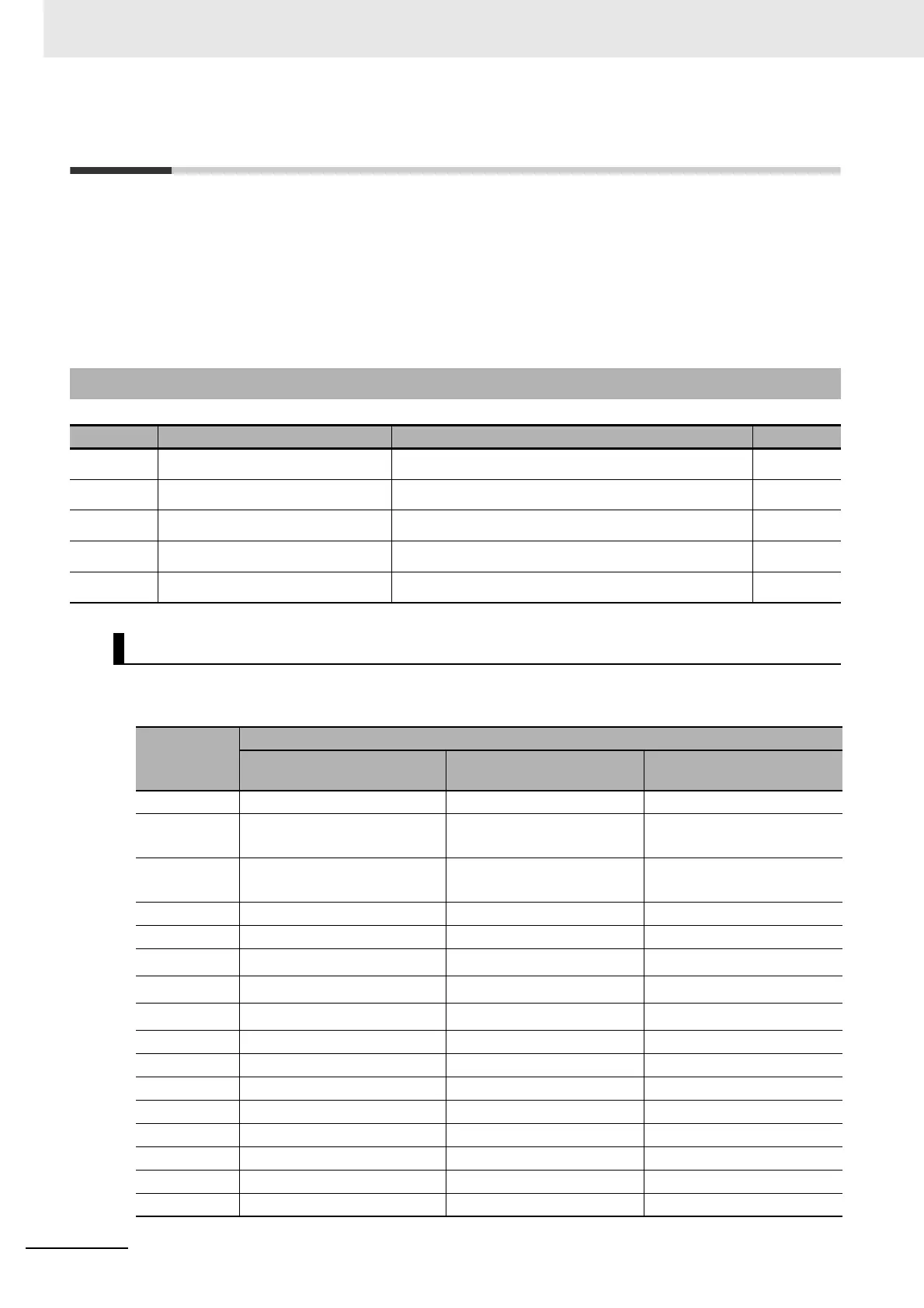
11-1-1 Objects Requiring Settings
Index Name Explanation Reference
3416 hex Analog Monitor 1 Selection Select the monitoring item for the analog monitor 1. page 9-33
3417 hex Analog Monitor 1 Scale Setting Set the output gain for the analog monitor 1. page 9-33
3418 hex Analog Monitor 2 Selection Select the monitoring item for the analog monitor 2. page 9-34
3419 hex Analog Monitor 2 Scale Setting Set the output gain for the analog monitor 2. page 9-34
3421 hex Analog Monitor Output Setting Select the analog monitor output method. page 9-34
Analog Monitor Objects (3416, 3417, 3418 and 3419 Hex)
3416 hex and
3418 hex set
value
Description
Monitoring item Unit
Output gain when 3417 hex
and 3419 hex are set to 0
0 Feedback Motor Speed r/min 500
1 Internal Command Motor
Speed
*1
r/min 500
2 Filtered Internal Command
Motor Speed
*1
r/min 500
3 Motor Control Effort r/min 500
4 Torque demand % 33
5
Position Error
*2
pulses (command units) 3,000
6
Pulse Position Error
*2
pulses (encoder units) 3,000
7
Fully-closed Error
*2
pulses (external encoder unit) 3,000
8 Hybrid Error pulses (command units) 3,000
9 P-N Voltage V 80
10 Regeneration Load Ratio % 33
11 Motor Load Ratio % 33
12 Forward Torque Limit % 33
13 Reverse Torque Limit % 33
14 Speed Limit Value r/min 500
15 Inertia Ratio % 500
 Loading...


