SS
SS
171
Characteristics
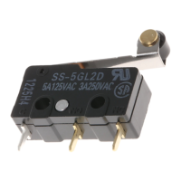
Operating speed
0.1 mm to 1 m/s (pin plunger models)
Operating frequency Mechanical: 400 operations/min max.
Electrical: 30 operations/min max.
Insulation resistance 100 MΩ min. (at 500 VDC)
Contact resistance
(initial value)
OF 1.47 N {150 gf}: SS-10, SS-5 models: 30 mΩ max.
SS-01 models: 50 mΩ max.
OF 0.49 N {50 gf}: SS-5 models: 50 mΩ max.
SS-01 models: 100 mΩ max.
OF 0.25 N {25 gf}: SS-01 models: 150 mΩ max.
Dielectric strength
(see note 2)
1,000 VAC (600 VAC for SS-01 models), 50/60 Hz for 1 min between terminals of the same polarities
1,500 VAC, 50/60 Hz for 1 min between current-carrying metal part and ground, and between each
terminal and non-current-carrying metal part
Vibration resistance
(see note 3)
Malfunction: 10 to 55 Hz, 1.5-mm double amplitude
Shock resistance
(see note 4)
Destruction: OF 1.47 N {150 gf}: 1,000 m/s
2
{approx. 100G} max.
OF 0.25 N {25gf}/0.49 N {50 gf}: 500 m/s
2
{approx. 50G} max.
Malfunction: OF 1.47 N {150 gf}: 300 m/s
2
{approx. 30G} max.
OF 0.25 N {25 gf}/0.49 N {50 gf}: 200 m/s
2
{approx. 20G} max.
Durability (see note 5) Mechanical: 30,000,000 operations min. (60 operations/min) (Refer to the following Engineering Data.)
10,000,000 operations min. (60 operations/min) for SS-10 models
Electrical: 200,000 operations min. (30 operations/min) (Refer to the following
Engineering Data.)
50,000 operations min. (30 operations/min) for SS-10 models
Degree of protection IEC IP40
Degree of protection
against electrical shock
Class 1
Proof Tracking Index (PTI) 175
Ambient operating
temperature
–25°C to 85°C (at ambient humidity of 60% max.) (with no icing)
Ambient operating
humidity
85% max. (for 5°C to 35°C)
Weight Approx. 1.6 g (pin plunger models)
Note: 1. The data given above are initial values.
2. The dielectric strength shown in the table indicates a value for models with a Separator.
3. For the pin plunger models, the above values apply for use at both the free position and total travel position. For the lever models,
they apply at the total travel position.
4. Lever-type models: Total travel position (with a contact separation time of 1 ms max.)
5. For testing conditions, contact your OMRON sales representative.
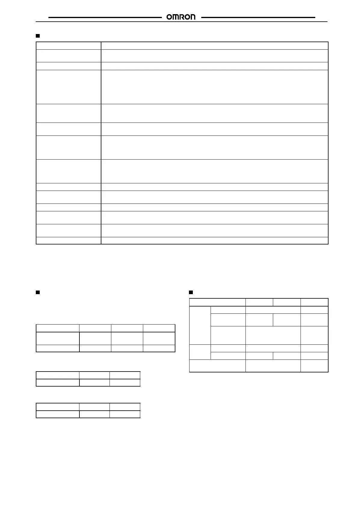
Approved Standards
Consult your OMRON sales representative for specific models with
standard approvals.
UL1054 (File No. E41515)/CSA C22.2 No. 55 (File
No. LR21642)
Rated voltage
SS-10 SS-5 SS-01
125 VAC
250 VAC
---
10.1 A
5 A
3 A
0.1 A
---
30 VDC --- --- 0.1 A
EN61058-1 (File No. 129246 for SS-5, 125256 for
SS-10, VDE approval)
Rated voltage
SS-10 SS-5
250 VAC 10 A 5 A
EN61058-1 (File No. J9451450, TÜV Rheinland
approval)
Rated voltage
SS-10 SS-5
250 VAC 10 A 5 A
Testing conditions: 5E4 (50,000 operations); T85 (0°C to 85°C).
Contact Specifications
Item
SS-10 SS-5 SS-01
Contact
Specification Rivet Crossbar
Material Silver
alloy
Silver Gold alloy
Gap
(standard
value)
0.5 mm 0.25 mm
Inrush
NC 20 A max. 1 A max.
current
NO 15 A max. 10 A max. 1 A max.
Minimum applicable
load (see note)
160 mA at 5 VDC 1 mA
at 5 VDC
Note: For more information on the minimum applicable load,
refer to
Using Micro Loads on page 175.
 Loading...