SS
SS
173
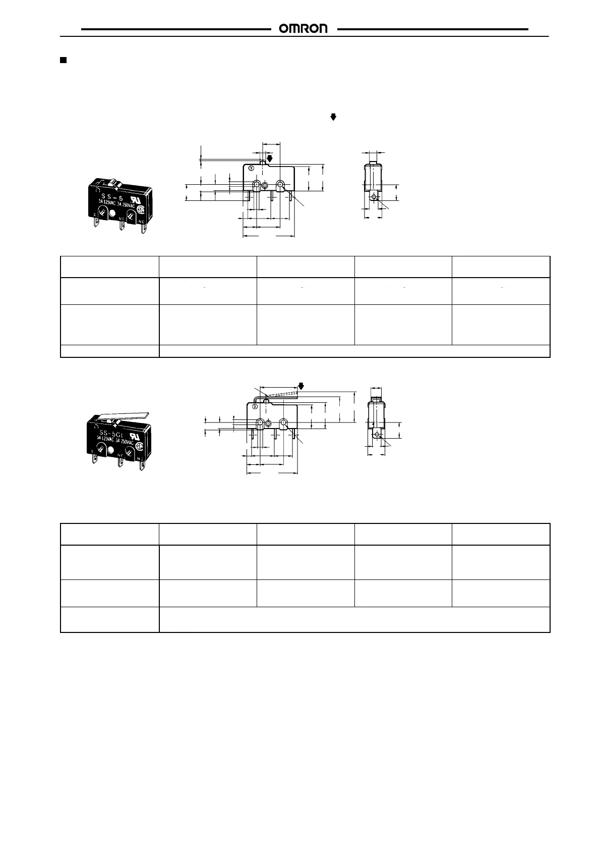
Dimensions and Operating Characteristics
Note: 1. All units are in millimeters unless otherwise indicated.
2. The following illustration and drawing are for solder terminal models. Refer to page 172 for details on models with quick-connect
terminals (#110) or PCB terminals.
3. Unless otherwise specified, a tolerance of ±0.4 mm applies to all dimensions.
4. The operating characteristics are for operation in the A direction (
).
Pin Plunger Models
SS-01(-E, -F)
SS-5(-F)
SS-10
2.35
+0.075
–0.05 dia. holes
2.35
+0.075
–0.05
Three, 1.6 dia.
10.2
9.5
7.5
2
PT
OP
6.4
2.9
2.5
1.6
8.8
7.3
5.1
19.8
2.5±0.07 dia.
3.2
6.4
3.2
6.4
9.5±0.1
A
Model
SS-01-E SS-01-F
SS-5-F
SS-01
SS-5
SS-10
OF max. 0.25 N {25 gf} 0.49 N {50 gf} 1.47 N {150 gf} 1.47 N {150 gf}
RF min.
0.25 N {25 gf}
PT max. 0.5 mm 0.5 mm 0.5 mm 0.6 mm
OT min. 0.5 mm 0.5 mm 0.5 mm 0.4 mm
MD max. 0.1 mm 0.1 mm 0.1 mm 0.12 mm
OP 8.4±0.5 mm
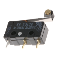
Hinge Lever Models
SS-01GL(-E, -F)
SS-5GL(-F)
SS-10GL
2.35
+0.075
–0.05
Three, 1.6 dia.
t = 0.3
(see note 1)
2.35
+0.075
–0.05 dia. holes
6.4
3.2
6.4
3.6
14.5 (see note 2)
FP
OP
10.2
9.5
2.5±0.07 dia.
2.5
2.9
8.8
7.3
5.1
Note: 1. Stainless-steel lever
2. Besides the SS-GL models with a hinge lever length of 14.5, the SS-GL11 models with a hinge lever length of 18.5, the
SS-GL111 models with a hinge lever length of 22.6, and the SS-GL1111 models with a hinge lever length of 37.8 are available.
Contact your OMRON representative for these models
19.8
9.5±0.1
1.6
A
Model SS-01GL-E SS-01GL-F
SS-5GL-F
SS-01GL
SS-5GL
SS-10GL
OF max.
RF min. 0.01 N {1 gf}
(reference value)
0.02 N {2 gf} 0.06 N {6 gf} 0.06 N {6 gf}
OT min. 1.2 mm 1.2 mm 1.2 mm 1.0 mm
MD max. 0.8 mm 0.8 mm 0.8 mm 1.0 mm
FP max. 13.6 mm
OP 8.8±0.8 mm
Note: The values indicated in parentheses are reference values for cases when the installation direction is such that the lever weight is not
applied to the plunger.
 Loading...