SS
SS
175
Precautions
Refer to pages 26 to 31 for common precautions.
Cautions
Terminal Connection
When soldering the lead wire to the terminal, first insert the lead wire
conductor through the terminal hole and then conduct soldering.
Make sure that the capacity of the soldering iron is 60 W maximum.
Do not take more than 5 s to solder the switch terminal. Improper
soldering involving an excessively high temperature or excessive
soldering time may deteriorate the characteristics of the Switch.
Be sure to apply only the minimum required amount of flux. The
Switch may have contact failures if flux intrudes into the interior of
the Switch.
Use the following lead wires to connect to the solder terminals.
Model
Conductor size
SS-5 0.5 to 0.75 mm
2
SS-10 0.75 mm
2
If the PCB terminal models are soldered in the solder bath, flux will
permeate inside the Switch and cause contact failure. Therefore,
manually solder the PCB terminal.
Wire the quick–connect terminals (#110) with receptacles. Insert
the terminals straight into the receptacles. Do not impose excessive
force on the terminal in the horizontal direction, otherwise the termi-
nal may be deformed or the housing may be damaged.
Insulation Distance
According to EN61058-1, the minimum insulation thickness for this
Switch should be 1.1 mm and minimum clearance distance be-
tween the terminal and mounting plate should be 1.6 mm. If the in-
sulation distance cannot be provided in the product incorporating
the Switch, either use a Switch with insulation barrier or use a Sepa-
rator to ensure sufficient insulation distance. Refer to Separator on
page 152.
Correct Use
Mounting
Turn OFF the power supply before mounting or removing the
Switch, wiring, or performing maintenance or inspection. Failure to
do so may result in electric shock or burning.
Use M2.3 mounting screws with plane washers or spring washers to
securely mount the Switch. Tighten the screws to a torque of 0.23 to
0.26 N m {2.3 to 2.7 kgf cm}.
Mount the Switch onto a flat surface. Mounting on an uneven sur-
face may cause deformation of the Switch, resulting in faulty opera-
tion or breakage in the housing.
Operating Stroke Setting
Take particular care in setting the operating stroke for the pin plung-
er models. Make sure that the operating stroke is 70% to 100% of
the rated OT distance. Do not operate the actuator exceeding the
OT distance, otherwise the durability of the Switch may be short-
ened.
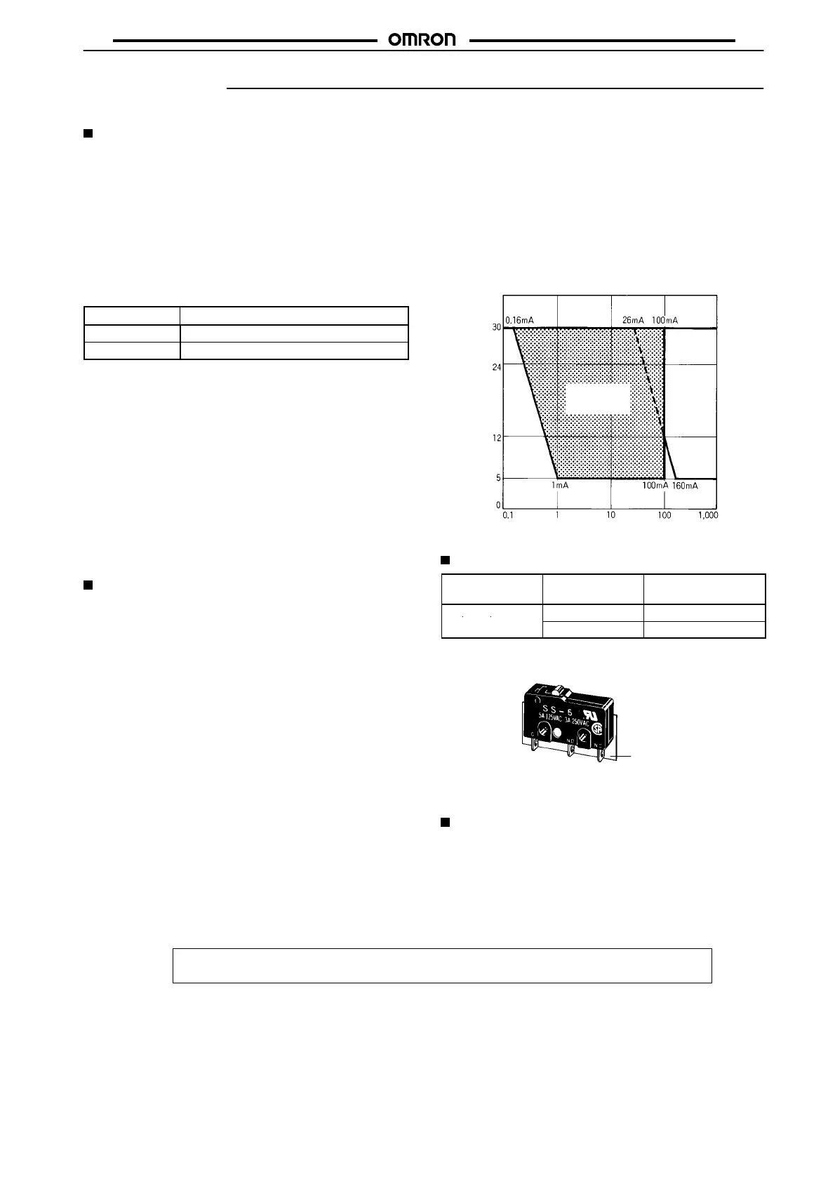
Using Micro Loads
Using a model for ordinary loads to open or close the contact of a
micro load circuit may result in faulty contact. Use models that oper-
ate in the following range. However, even when using micro load
models within the operating range shown below, if inrush current oc-
curs when the contact is opened or closed, it may increase contact
wear and so decrease durability. Therefore, insert a contact protec-
tion circuit where necessary.
The minimum applicable load is the N-level reference value. This
value indicates the malfunction reference level for the reliability lev-
el of 60% (λ 60). The equation, λ 60 = 0.5 10
–6
/operations indi-
cates that the estimated malfunction rate is less than 1/2,000,000
operations with a reliability level of 60%.
Operating range
for micro load
models SS-01
Operating
range for
general-load
models
SS-5, SS-10
Current (mA)
Voltage (V)
Inoperable
range
Separators
Applicable
Switch
Thickness (mm) Model (see note)
SS, D2S, D2SW
0.18 Separator for SS0.18
0.4 Separator for SS0.4
Separator
Separator for SS
Note: The material is EAVTC (Epoxide Alkyd Varnished Tetron
Cloth) and its heat-resisting temperature is 130°C.
Connector
Refer to Terminal Connectors on page 282.
ALL DIMENSIONS SHOWN ARE IN MILLIMETERS.
To convert millimeters into inches, multiply by 0.03937. To convert grams into ounces, multiply by 0.03527.
Cat. No. B032-E1-11C
 Loading...