-3-
-4-
1. Hold the button (minimum 3 and less than 5 seconds) until [ ] blinks
without a workpiece.
2. When [ ] starts blinking, release the button.
The display changes [ ] [ ] and 1-point tuning is completed.
The measured value display returns.
Used to judge the presence/absence of a workpiece by referring to the pre-determined
background (reference surface).
Used to assign the upper and lower limits to one actual workpiece and judge
if the workpiece is within the range.
●
1-point Tuning
2. Hold the button (3 to less than 5 seconds) until [ ] blinks with a workpiece
to detect on the reference surface.
1. Set the AREA item in the menu to "ON" and return to the measured value display.
3. When [ ] starts blinking on the display,
release the button.
●
1-point Area Tuning
(3) Detect for Workpiece Presence/Absence
(Tuning Only Using Reference Surface)
(5) Set Plus/Minus (±) Tolerance
●
Threshold Value Setting
The OUT1 indicator keeps blinking while "Threshold 1/ Threshold 1H/ Threshold 1L"
is being changed.The OUT2 indicator keeps blinking while "Threshold 2/ Threshold
2H/ Threshold 2L" is being changed.
(
2
)
Detect for Workpiece Presence/Absence
1. Press the button (within 1 sec.) once without a workpiece.
3. Set the workpiece at the desired lower limit and lightly press the button.
To loosen or tighten the ON/OFF switching conditions, use the buttons for
minute adjustment of the threshold values.
The order of the workpiece does not matter.
Used to distinguish between two objects with different height from the Sensor e.g.
OK and NG, workpiece and background (reference surface) or workpieces A and B.
●
2-point Tuning
2. Lightly press the button once again with a workpiece.
The display changes [ ] [ ]
and 2-point tuning is completed.
The measured value display returns.
The order of the workpiece does not matter.
Increase threshold
Decrease threshold
Refer to " 7. Area Output, Detailed Settings"
To set plus and minus threshold values using "0" as the background, use the zero
reset function to reset the distance to "0". Then, perform 1-point area tuning.
The display changes [ ] [
t-p1
] [ ].
0.00
Hold for 3 to
less than 5 sec
until [ ] blinks.
TUNE
TUNE
TUNE
TUNE
TUNE
TUNE
TUNE
UP/DOWN
t-p1
t-p2
Setting is Completed
t-p1
Setting is Completed
t-p2
The display changes [ ] [ ] and 2-point tuning is completed.
The measured value display returns.
Setting is Completed
Hold for 3 to
less than 5 sec
until [ ] blinks.
t-p1
Setting is Completed
Refer to "
Convenient Setting Features (1)"
Refer to " Error Messages" .
2. The channel display changes in the following sequence
by pressing the button.
3. Press the button to return to measurement mode.
1. Briefly press the button in Measurement
mode.
●
CH Setting Mode
(
1
)
Switch Channel to Set Threshold
ch-1
ch-2
ch1h
ch1l
ch2h
ch2l
<Area Output is ON>
Threshold 1 Threshold 2
Threshold 1H Threshold 1L Threshold 2H Threshold 2L
ch-1
0.00
UP/DOWN
UP/DOWN
MODE
1. Hold the button (5 sec. or longer) until [ ] blinks rapidly without a workpiece.
(6) When (2) to (5) Methods Failed
Used to judge the presence/absence of a workpiece using the pre-determined background
(reference surface) as the reference. Unlike 1-point tuning, this method focuses on the detection
of the absence of workpiece. Insufficient light level or outside-range errors caused by
complicated workpiece appearance are judged as "the presence of the workpiece".
Used to assign the upper and lower limits to the distance from the reference surface and judge
if a workpiece is within the range. Unlike 2-point tuning, this method focuses on the detection of
the absence of workpiece. Insufficient light level or outside-range errors caused by complicated
workpiece appearance are judged as "the presence of the workpiece".
2. When [ ] in the display starts blinking rapidly, release the button.
●
Tuning mode without Workpiece (Area Output is OFF)
●
Tuning mode without Workpiece (Area Output is ON)
Threshold H
Threshold
Threshold L
Reference surface
Reference surface
ON
OFF
OFF
ON
ON
<Tuning mode without Workpiece> <Area Tuning mode without Workpiece>
TUNE
TUNE
Sensor Sensor
Hold for 3 to
less than 5 sec
until [ ] blinks
rapidly.
Setting is Completed
1. Select "ON" for area output in menu setting mode to return to measurement mode.
●
2-point Area Tuning
2. Set the workpiece at the desired upper limit and lightly press the button.
(4) Set Upper Limit and Lower Limit (Using Area Output)
Refer to " 7. Area Output, Detailed Settings"
Used to judge if the workpiece is within the range by using the upper limit and
lower limit workpieces.
TUNE
t-p1
The display changes [ ] [
t-p1
] [ ].
pnt 2
Fine Adjustment of Threshold Value
2-4
③
Settings
2
Tuning
2-3
2-2
Setting and Display Overview
Output and Threshold Value
2-1
MODE
UP/DOWN
Hold for
min. 3 sec.
Less than 3 sec.
Menu Setting mode
Refer to "2-3 (1)".
CH Setting mode
Measurement mode
0.00
MODE
Less than 1 sec.
Threshold Setting mode
ch-1
No operation for min. 2 sec.
10.00
■
Switching to Individual Modes
■
Other Button Operation
Tuning
Zero reset setting
Zero reset cancel
Key lock setting/
cancel
button
button+button
simultaneouslyforlessthan3sec.
button+button
simultaneouslyformin.3sec.
button+button
simultaneouslyformin.3sec.
Refer to "2-4".
Refer to "2-3"
Refer to "
③
(2)"
Refer to "
③
(1)"
Refer to "
③
(1)"
<Area Output is OFF> <Area Output is ON>
Measured value
CH1 CH1
OUT1 OUT2
CH2 CH2
OFF
OFF
OFF
OFF
OFF
OFF
Threshold
1
Threshold
2
Threshold
1H
Threshold
1L
Threshold
2H
Threshold
2L
Measured value
Measured value Measured value
OUT1 OUT2
MODE
UP/DOWN
UP/DOWN
UP/DOWN
TUNE
TUNE
TUNE
ON ON
ON ON
• TUNE1 input (external input terminal) can also replace the button operations
for tuning to CH1.
Tuning can be performed for TUNE2 to CH2.
•
When performing tuning, threshold values are recorded in EEPROM (non-volatile
memory) in the sensor. The writing life of EEPROM is 100,000 times. Be careful of
writing life when performing measurement-by-measurement tuning.
• The allocation of button and external input terminals can be fixed by
changing the tuning type.
Refer to " 2.Tuning Type, Detailed Settings"
Refer to "2-3 (1)", "2-3 (4)"
Refer to "2-3 (2)", "2-3 (3)"
Refer to "2-3 (5)"
1-point tuning
2-point tuning
Tuning mode without workpiece
CH setting mode
TUNE
Press button for 3 to 5 seconds.
Press button once for the 1st point.
Press button once for the 2nd point.
Press button for 5 seconds.
■
Quick Reference for Tuning Operation (Perform tuning after selecting a CH)
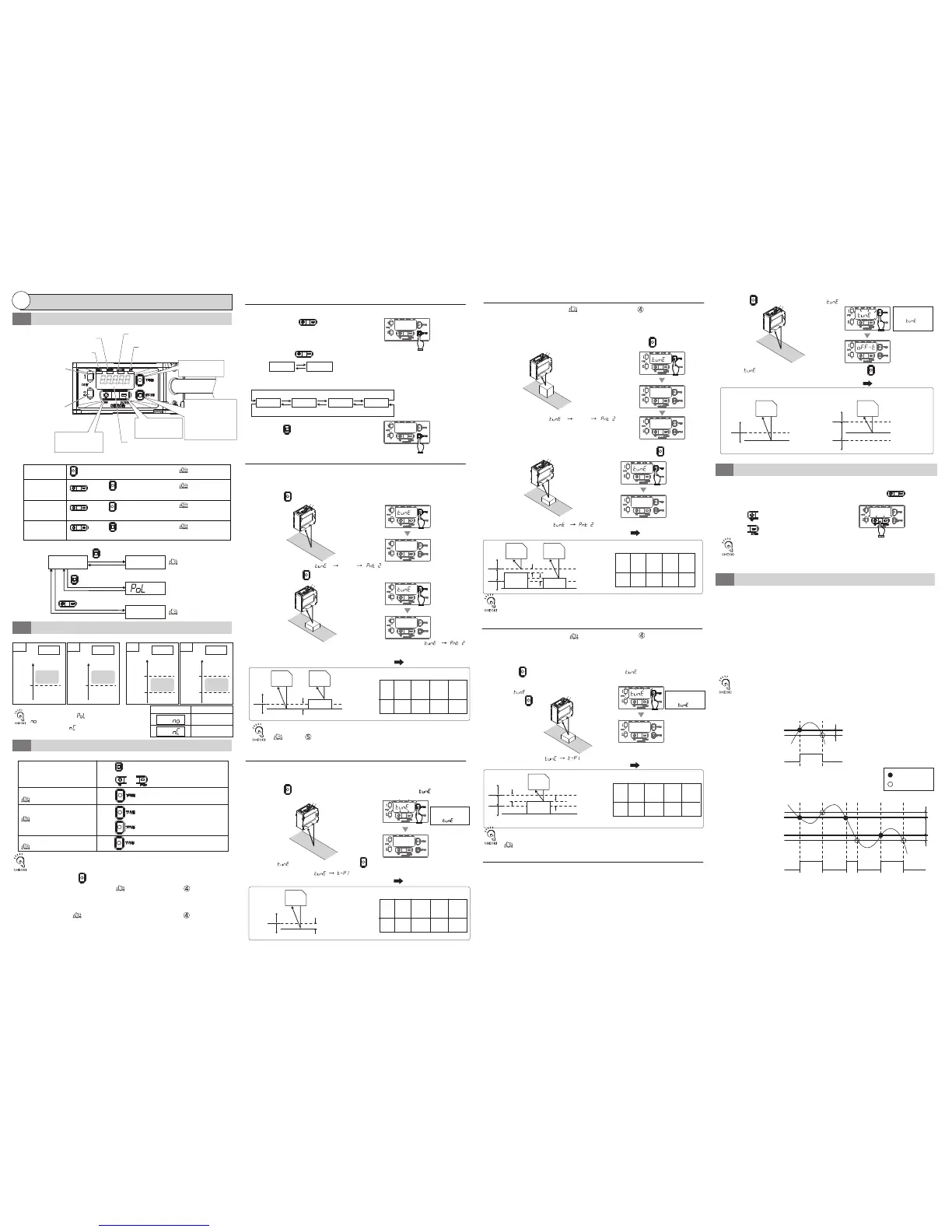
(Near)
(Far)
. . . .
[ZERO]Zero reset indicator (Orange)
[ST]Smart tuning indicator (Blue)
OUT2 Output indicator
Orange)
OUT1 Output indicator
(Orange)
Turns ON when tuning is performed with the background
suppression function ON.
Turns ON in MENU setting mode.
[MENU]Menu Indicator (Orange)
[LD ON]Laser ON indicator (Green)
Turns ON when zero reset is set.
Turns ON when sensor is emitting laser.
Digital display
Displays the displacement volume in
Measurement mode and setting
item/setting value in other modes.
■
Nomenclature and Function
Turns ON when the value
exceeds Threshold 1 or within
the range of 1L to 1H.
Turns ON when the value exceeds
Threshold 2 or within the range
of 2L to 2H.
[TUNE]button
Used to perform tuning.
[MODE]button
Switches between
Measurement mode and MENU
setting mode by holding it for
3 seconds or longer. Switches
to CH Setting mode when it is
pressed less than 3 seconds.
[DOWN]button
Used to change a
threshold value or select
a setting item.
[UP]button
Used to change a
threshold value or select
a setting item.
Refer to " 5. Background suppression function, Detailed Settings"
88888
The display changes [ ] [ ] and 1-point area tuning is completed.
The measured value display returns.
Sensor
Threshold
H
D
D 0.13 0.4 2 9
Threshold
L
Sensor
Lower limit
workpiece
ON
OFF
OFF
The margin (D) for the upper/lower limit of
each model is as follows (fixed value):
Model
ZX1-
LD50
□
ZX1-
LD100
□
ZX1-
LD300
□
ZX1-
LD600
□
D
Background
(Reference surface)
Upper limit
workpiece
Unit (mm)
D
D
0.13 0.4 2 9
ON
OFF
OFF
D
ZX1-
LD50□
ZX1-
LD100□
ZX1-
LD300□
ZX1-
LD600□
Sensor
Workpiece
Threshold H
Threshold L
Background
(Reference
surface)
The margin (D) for the upper/lower limit of
each model is as follows (fixed value):
Model
Unit (mm)
The above figures represent the behaviors when
the output polarity [ ] is set to normally-open
[ ] (initial value). If the polarity is set to
normally-closed [ ], the ON/OFF polarities in
the figures are reversed.
Output polarity
Output at detection
ON
OFF
Press button to enter CH setting mode, and then
press or button to select a CH.
MODE
•
When setting the background suppression function to ON and performing tuning,
the measurement value and sensitivity level can be limited according to the sensitivity.
Use it when abnormal distance is detected due to diffuse reflection caused by surrounding walls, etc.
Sensor
Threshold
Reference surface
Sensor
Workpiece
ON
OFF
Without workpiece
0.2 0.7 3 15
D
ZX1-
LD50□□
ZX1-
LD100□□
ZX1-
LD300□□
ZX1-
LD600□□
The margin (D) for the Threshold of
each model is as follows (fixed value):
Model
Unit (mm)
D
Threshold
Reference surface
Without workpiece
Sensor
ON
OFF
0.2 0.7 3 15
D
ZX1-
LD50□□
ZX1-
LD100□□
ZX1-
LD300□□
ZX1-
LD600□□
The margin (D) for the Threshold of
each model is as follows (fixed value):
Model
Unit (mm)
D
Fine Adjustment of Hysteresis Width
2-5
●
Hysteresis Width Setting
A minute step can be judged by adjusting the hysteresis width according to the
workpiece. However, note that the judgment output varies if lowering the hysteresis
width while the displacement value is varying due to moving workpiece or low
reection light intensity.
●
What is Hysteresis Width?
A point in which a judgment output turns from OFF to ON is called an operating
point, and a point in which a judgment output turns from ON to OFF is called a return
point. On this sensor, threshold means operating point, and a distance to the return
point can be set based on the hysteresis width.
Note that the direction where the hysteresis width is set for the threshold differs
depending on ON/OFF of the area output.
Threshold
HysteresisWidth
HysteresisWidth
Judgmentoutput
Judgmentoutput
AreaoutputisOFF
Measuredvalue
Measuredvalue
AreaoutputisON
Operatingpoint
Returnpoint
ON
OFF
ThresholdL
ON
OFF
ThresholdH

 Loading...