Replacement Onan
®
300-4296(12V)
300-4297 (24V)
ENGINE MONITOR
(FS Part No. 56-4296-00
or 56-4297-00)
FLIGHT SYSTEMS
207 Hempt Rd. Mechanicsburg, PA 17050 Ph: 717-590-7330 www.flightsystems.com
Designed & Built in USA by
Thank you for choosing Flight Systems P/N 56-4296-00 for the replacement of Onan
®
P/N 300-4296 (12V), or P/N 56-
4297-00 for the replacement of Onan
®
P/N 300-4297 (24V). It will replace all revisions of the original Onan
®
product
on systems using 2 to 12 lights. Revisions made by Onan
®
over a period of about three decades include the following:
• Glass fuses replaced by AT-type blade fuses
• Addition of TB3
• Addition of feature selection jumpers
• AdditionofW10toselectashingorsteadyforSWITCHOFFindication
• Addition of diagnostic LEDs to aid in troubleshooting
• ACstartdisconnect(K10)changedfromanACrelaytoaDCrelay
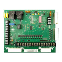
You will notice that this new Flight Systems replacement board looks quite different from any of the Onan
®
boards.
The most striking difference is the microprocessor-based design which enhances reliability and eliminates 17 of the 20
relays. Additional features include:
• Auto-reset on initial power-up
• Plainly marked DIP switches for feature selection (no jumpers)
• Plainly marked, user-friendly, on-board LED array for easier system troubleshooting
• Solid-stateACvoltagesensingforcranktermination
• Surge and reverse polarity protection
• Reverse polarity indication warns of incorrect battery connection
• Commonalarmoutputisupgradedto5A
• Solid-state outputs for annunciators
• Lamp test for both local and remote annunciators
• Crankinglimitedto60secondswhencontinuouscrankisselected
• Network communications capability possible with Modbus option
You will also notice that the diagnostic LEDs are arranged in an orderly and easy-to-read fashion and that DIP switches
have replaced movable jumpers for feature selection. Table 1 below shows how to set the DIP switches. The “ON”
position is always to the right. For example, FAULT 1 is set up using S1, S2 and S3. If S1 is ON, FAULT 1 is enabled
15 seconds after RUN is detected. If S1 is OFF, FAULT 1 is enabled immediately when RUN is detected, without any
delay. If S2 is ON, FAULT 1 will cause a shutdown. If S3 is ON, FAULT 1 is enabled always, running or not, there
is no shutdown and the settings of S1 and S2 do not matter. In other words, S3 must be OFF to enable the selection
of delay or shutdown using S1 and S2. FAULT 2 works exactly the same way using S4, S5 and S6. The settings for
S7 through S10 are explained, along with the factory settings for all of the DIP switches in Table 1 - SEE REVERSE.