1
Photoelectric detectors detect intruders when both the upper and lower invisible infrared beams are simultaneously broken.
Maximum detection range between Transmitter and Receiver for the AX-250PLUS is 250ft. (75m), the AX-500PLUS is 500ft. (150m) and for the
AX-350TF is 350ft. (100m), the AX-650TF is 650ft. (200m)
FEATURES
• Beam interruption time adjustment
• Anti-Frost Structure
• Alignment level monitor jack
• Form C relay
• Tamper
• Option
• UL Listed
: This function allows you to select the suitable beam interruption time for any environment.
: Prevents fog and condensation from blocking the beams.
: Can easily obtain maximum optical alignment by checking the voltage from this jack.
: Form C relay for more applications.
: N.C., Opens when cover is removed.
: Heating unit (HU-1), Back cover (BC-1) AX-Beam Tower (AX-BT)
:
For UL Listed applications, the heating unit (HU-1) shall not be installed with the models AX-350TF and AX-650TF.
AX-350TF, AX-650TF ONLY
• LED indicator for fi ne beam alignment level
• Selectable beam frequencies
• Re-Transmit Circuit
• D.Q.Circuit (Environmental Disqualifi cation)
• Alarm Memory
: The optical alignment level can be checked at the Reciver.
: Crosstalk is eliminated with 4, channel selectable, beam frequencies. Used when stacking beams
or for long range applications.
: The advantage of this method is the elimination of wiring, from a detector or switch, back to the
control panel.
: The environmental compensation circuit is designed to eliminate false alarms caused by snow,
fog, heavy rain, ice and misalignment.
For Safe Use of the Product
• Read this instruction manual carefully prior to installation.
• After reading, store this manual carefully in an easily accessible place for reference.
• This manual uses the following warning indications for correct use of the product and harm to you or other people and damage to your assets, which
are described below. Be sure to understand the description before reading the rest of this manual.
WARNING
Failure to follow the instructions provided with this indication and improper handling may cause death or serious injury.
CAUTION
Failure to follow the instructions provided with this indication and improper handling may cause injury
and / or property damage.
This symbol indicates prohibition. The specifi c prohibited action is provided in and/or around the fi guer.
This symbol requires an action or gives an instruction.
WARNING
Do not use the product for purposes other than the detection of moving objects such as people and vehicles.
Do not use the product to activate a shutter, etc., which may cause an accident.
Do not touch the unit base or power terminals of the product with a wet hand (do not touch when the
product is wet with rain, etc.). It may cause electric shock.
Never attempt to disassemble or repair the product. It may cause fi re or damage to the devices.
Do not exceed the voltage or current rating specifi ed for any of the terminals during installation, doing so
may cause fi re or damage to the devices.
CAUTION
Do not pour water over the product with a bucket, hose, etc. The water may enter, which may cause damage
to the devices.
Clean and check the product periodically for safe use. If any problem is found, do not attempt to use the
product as it is and have the product repaired by a professional engineer or electrician.
INSTALLATION MANUAL
No. 59-1365-4 0902-05
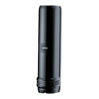
PHOTOELECTRIC DETECTOR
AX-250PLUS, AX-500PLUS
AX-350TF, AX-650TF
1.PARTS IDENTIFICATION ····································· P2
2.PRECAUTIONS ····················································· P2
3.INSTALLATION METHOD ···································· P3
4.AX-250/500PLUS
4-1.TERMINAL ······················································ P4
4-2.WIRING ··························································· P4
4-3.OPTICAL ALIGNMENT ·································· P5
5.AX-350/650TF
5-1.TERMINAL ······················································ P6
5-2.WIRING ··························································· P6
5-3.OPTICAL ALIGNMENT ·································· P7
6.BEAM INTERRUPTION
TIME ADJUSTMENT ············································ P8
7.AX-350/650TF
7-1.SELECTABLE BEAM FREQUENCIES ·········· P8
7-2.ALARM MEMORY ·········································· P8
7-3.DQ CIRCUIT ··················································· P9
7-4.RE-TRANSMITTING CIRCUIT ······················· P9
8.SPECIFICATIONS ··············································· P10
9.DIMENSIONS ······················································ P10
10.TROUBLE SHOOTING
CHECK SHEET ············································ P11,P12
CONTENTS
< STANDARD >
< 4 SELECTABLE BEAM FREQUENCIES >
Please read intsructions completely before beginning installation.