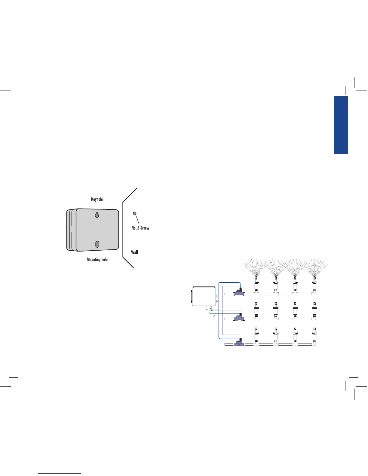
2. Mounting the Sprinkler Timer
• Use the mounting template (included) to mark the screw
locations on the wall.
• Insert a No. 8 screw (included) in the upper mark, leaving
the screw head about 1/8” (3mm) out from the wall. (Use the
expanding anchors in plaster or masonry if necessary.)
• Slip the keyhole slot in the back of the sprinkler timer over the
extended screw. [See Figure 12b]
• Screw a No. 8 screw through the hole located behind the wire
shroud cover.
3. Install the Batteries
One Lithium battery (CR2032) is required to retain the program in
memory during power loss. Annual replacement is recommended.
• See page 3 for battery replacement
Note: The battery alone will not operate the valves in your sprinkling
system. The sprinkler timer has a build-in transformer that must be con-
nected to an AC line voltage source.
4. Wiring the Electric Valves
Note: If the distance between the sprinkler timer and valves is under 700’
(210 m), use Orbit
®
sprinkler wire or 20 gauge (AWG) plastic jacketed
thermostat wire to connect the sprinkler timer to the valves. If the distance
is over 700’ (210 m), use 16 gauge (AWG) wire.
• Taking the sprinkler wire, strip 1/2” (12 mm) of the plastic
insulation off the end of each individual wire.
• Connect one wire from each valve (it doesn’t matter which
wire) to a single “Common” sprinkler wire (usually white)
[See Figure 13]
Important: All wires should be joined together using wire nuts, solder,
and/or vinyl tape. For additional protection to waterproof connections,
an Orbit
®
grease cap can be used.
• Next connect the remaining wire from each valve to a separate
colored sprinkler wire.
• To avoid electrical hazards, only one valve should be connected
to each station.
Important: The wire can be buried in the ground; however, for more
protection wires can be pulled through PVC pipe and buried underground.
Be careful to avoid burying the wires in locations where they could be
damaged by digging or trenching in the future.
Figure 13: Connecting Sprinkler Wires to Valves
 Loading...