2
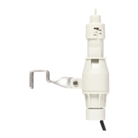
The unit has a sensing angle of 360° and can detect
up to 5 meters radius at the mounting height of 2.2
meters or 7 meters radius at the mounting height of
5 meters. (FIGURE 3)
FIGURE 3
Wiring Instruction:
(1) Switch off the power source or wall switch.
(2) Strip approximately 6-8mm insulating part of the
power supply wire. Connect the power cord to
power supply wire using the wire nuts provided.
(3) Study the following figure for wiring information.
The power cords of “LS” and “N” marks are to be
connected to the lighting fixture. (FIGURE 4)
Warning: Incorrect wiring could damage the
sensor or connected load, and also may cause
electrical harm.
FIGURE 4
(4) In order to install the sensor to the ceiling, drill a
diameter of 68mm round hole on the ceiling.
Wedge the main body into the round hole directly.
(FIGURE 5)
FIGURE 5
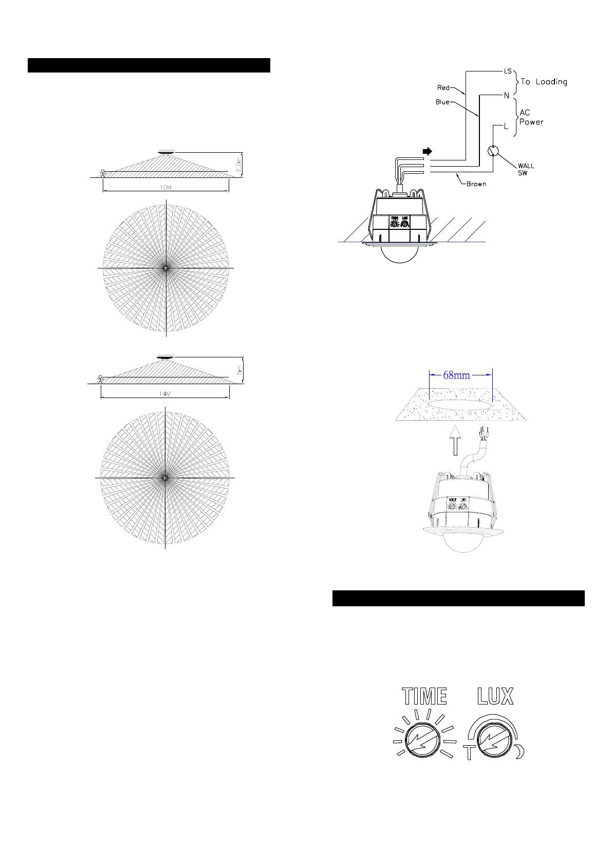
SETTING THE LIGHTING SYSTEM
(1) TEST MODE
Turn the Lux control and the Time control
counter-clockwise to the edge-the TEST position.
(FIGURE 6)
FIGURE 6
 Loading...