For Technical Support: www.panduit.com/resources/install_maintain.asp
INSTALLATION INSTRUCTIONS
© Panduit Corp. 2017
PN600A
Page 2 of 4
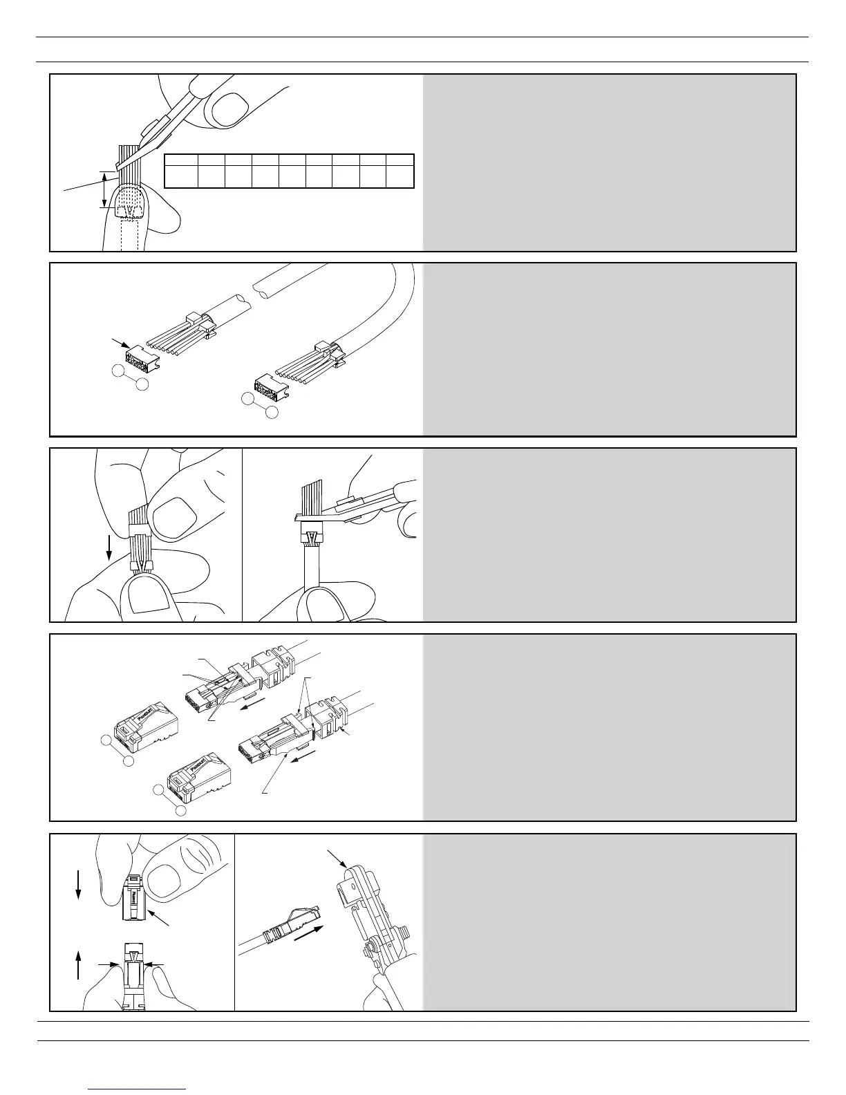
• Guide conductors into load bar holes while holding
conductors in the divider.
• Slide load bar towards divider until flush.
• Ensure the divider/load bar is centered and perpendicular to
the cable axis.
• Trim conductors flush with load bar face.
• Orient load bar with contact slots facing downward.
Verify
load bar
orientation
5
(Cable end 1)
(Cable end 2)
1
8
Pins
1
8
Pins
• Straighten and align untwisted conductors using a circular
motion while holding conductors in respective divider slots.
• Maintain grip of conductors in T568B wiring scheme.
• Trim conductors on an angle approximately 1.00" from
divider leading edge.
4
1.00"
T568B BRN
8
WHT
7
BRN/
6
GRN
WHT
5
BLU/
4
BLU
WHT
3
GRN/
2
ORG
WHT
1
ORG/
Pin #
(Cable end 1)
• Grip the strain relief collar and insert cable sub-assembly into
the plug housing. (Fig. 9)
• Push sub-assembly into housing until collar locking tabs
engage the plug housing pocket. Although not required, TX6
PLUS Plug Assembly Tool (CSPT) is available to facilitate this
step.
• Use tool MPT5-8AS to complete plug termination. (Fig. 10)
• Trim or press excess drain wire between the collar latches.
• Push up boot and engage with collar latches.
• Visually check plug. Assembly is complete.
Drain wire
(Cable end 2)
(Cable end 1)
Strain collar
guides
Collar latches
Boot position
when using
CSPT
Pins
Collar barbs
1
8
Pins
1
8
Collar locking
tabs
• Orient cable so the drain wire is facing up.
• Hold the load bar and divider stationary while sliding the strain
relief collar forward until there is no gap between the collar
and divider.
• Ensure the drain wire is routed through the strain collar
guides.
• Confirm the cable jacket extends beyond the collar barbs.
• Align pin #1 of cable sub-assembly (cable, load bar, divider,
and strain relief collar) with pin #1 of plug housing.
8
 Loading...