19 GB/IE
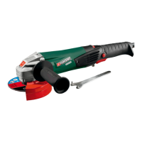
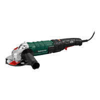
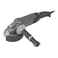
Use angle grinders that have a cutting disc
diameter of 115 or 125 mm only.
Do not allow anyone else to
come within the working range of
the product while you are using it.
Grip the handle tightly when using the angle
grinder and position your body and arm to
allow you to resist kickback forces.
Do not “jam” the wheel or apply excessive
pressure. Do not attempt to make an exces-
sive depth of cut. Overstressing the wheel
increases the loading and susceptibility to
twisting or binding of the wheel in the cut
and the possibility of kickback or wheel
breakage.
When the wheel is binding or when inter-
rupting a cut for any reason, switch off the
power tool and hold the cutting unit motion-
less until the wheel comes to a complete stop.
Never attempt to remove the wheel from the
cut while the wheel is in motion otherwise
kickback may occur. Investigate and take
corrective action to eliminate the cause of
wheel binding.
Do not restart the cutting operation in the
workpiece. Let the wheel reach full speed
and carefully re-enter the cut. The wheel may
bind, walk up or kickback if the power tool
is restarted in the workpiece.
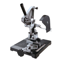
Assembly
CAUTION! DANGER OF FIRE! Assem-
ble and use the product on a fire-resistant sur-
face only.
Follow these steps:
Fasten the saddle
21
on to the base plate
20
with the hexagonal socket head screws
23
and washers
22
(see Fig. A).
Fasten the handle
3
on to the mount
24
with
the projecting screw thread and the cor-
responding
nut (see Fig. A).
Note: Please bear in mind that the angle
grinder must be fitted with a suitable cutting
disc before assembly. It is not possible to
change the disc with the angle grinder in-
stalled in the product.
Now prepare for mounting the angle grinder
in the mount
24
.
Note: At this point, first check the size of
the handle thread of your angle grinder. It
may be M6, M8 or M10.
Then place the corresponding mounting
bolts
8
, washers
7
and matching nuts
9
,
distance pieces
10
and plastic bushings
6
to one side, ready for use.
Insert the necessary plastic bushings
6
into
the mounting pieces
11
,
26
(see Fig. B).
Note: Ensure that the size of the plastic
bushings
6
matches the required mounting
bolts
8
. Plastic bushings are not required
for mounting bolts M10
8
.
Screw the matching mounting bolt
8
through the rear mounting piece
26
(see
Fig. B).
Fasten the rear mounting piece
26
in place
by tightening the corresponding size of nut
9
on the mounting bolt
8
(i.e. by
turning it
in the direction of the mounting piece
26
)
(see Fig. B).
Insert the adjustment screw
13
through the
bottom hole and the adjustment screw
1
through the top hole of the mount
24
(see
Fig. E). Note that later the rubber buffers of
these screws must lie against the angle
grinder housing.
Note: First insert these screws so that the rub-
ber buffers lie directly against the mount
24
.
Now push the plastic locating pieces
12
of
the mounting pieces
11
,
26
on to the guide
of the mount
24
(see Fig. B).
Then attach the mounting pieces
11
,
26
through the plastic locating pieces
12
with
the hexagonal socket head screws
19
in the
elongated holes in the mount
24
(see Fig. B).
Place the desired distance piece
10
on the
mounting bolt
8
and washer
7
on to the
front mounting piece
11
(see Fig. D).
Note: The three distance pieces
10
are for
choosing the most appropriate cutting depth.
Note: Set the distance piece
10
so that the
cutting disc cannot come into contact with
 Loading...