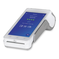
The following items are included with your POS
t
erminal. If any items are missing, contact your dealer.
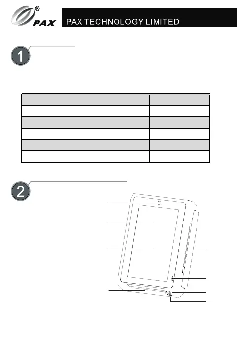
Figure 1:
Fron
t vi
ew
Figure 3: View from all sides
Name Quantity
IM30 POS terminal 1
IM30 mounting bracket 1
M4 nuts 4
M4 screws 4
Contents
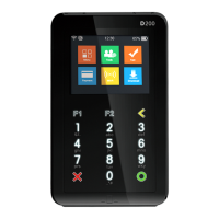
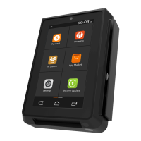
Product Description
1.
LCD touchscreen
2. front facing camera
3.
magnetic strip card reader
4.
smart card reader
Figure 2: Back view
1.
RS232-A (device)
2.
RS232-B (
host)
3.
auxiliary j
ack (mic + speaker)
4.
Ethernet port
5.
digitial I/O
6.
Executive/MDB port
7.
3G/4G a
ntenna (optional)
9
.
USB Type A port (host)
10.
USB Type C port (OTG)
11.
service button
12.
reset button
13.
HDMI port
14.
MDB port
IM30 Quick Setup Guide 1
Front
Left
Right
Top
Bottom
Back
1)
SAM and SIM Cards
Inst
allation
Figure 5: SAM and SIM card mounts (SAM module)
Unscrew the SAM card module and then remove it by
prying at the notch set to its side. On the main body of
the IM30, there are 2 micro-SIM sized SAM card slots.
Open the mount and insert the card into the slot with
the clipped corner of the card to the upper right, then
lock the mount with the card inside.
5
.
code scanning camera
6.
camera locator light
7.
status indicator
The SAM card module comes in 3 configurations, the
first has no functional card slots, the second has a
mini-SIM sized SIM card slot located to the left, and
the last has an additional 2 mini-SIM sized SAM card
slots to the right of the SIM card slot. Install the cards
with the clipped corner facing inwards and to the right.
1
2
3
4
5
6
7
1
2
3
4
5
6
7
8
9
10
11
12
13
14
Figure 4: SAM card mounts (main body)
8.
SAM card module
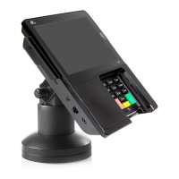
Figure 7
: installation and mounting
Instructions
S
torage Temperature:
Relative Humidity:
-30°C~70°C
(-22°F~158°F)
5%
~
95% (no condensation)
Working Temperature:
-
2
0°C~70°C (-4F~158°F)
2
)
Environmental Conditions
Maintenance and Usage
5
1)
If any cables become damaged, seek a replacement.
2)
3)
Do not insert unknown materials
into any port on
the IM30, this may cause serious damage to the device.
4)
If repairs are required, please contact a professional
technician instea
d of attempting them on your own.
5)
The IM30 contains tamper-proofing features;
these
circuits will trigger if the device is disassembled, at
which point it
will have to be rearmed before the
device is ready to resume operation.
6)
The IM30 is designed for indoor use; however, during
normal use its surface should still be keep clear of
dirt
and possible liquid contaminants.
While the IM30 is designed to resist ingress of dust and
liquids, it is not designed to resist pressurized liquids
such as water hoses. Keep the back of the device away
from dust and liquids as much as possible.
1)
2)
Clearance Holes and Dimensions
Figure 6: device dimensions (mm)
Switching the device on and off
Switch off:
Link the
IM30 to a power source via the
MDB, Executive, or RS232-A ports.
Switch on:
Disconnect the IM30 from the power
terminal it is connected to.
3)
Recommended Device Installation
7)
Make sure the various cables connect t
o provi
de the
appropriate voltages at the proper pins.
IM30
M4 nuts
M4
screws
mounting bracket
105.00
146.00
31.50
56.67
82.00
107.00
1 2
3
4
5 6
8
contactless card interface
8.
 Loading...