Electrical 9
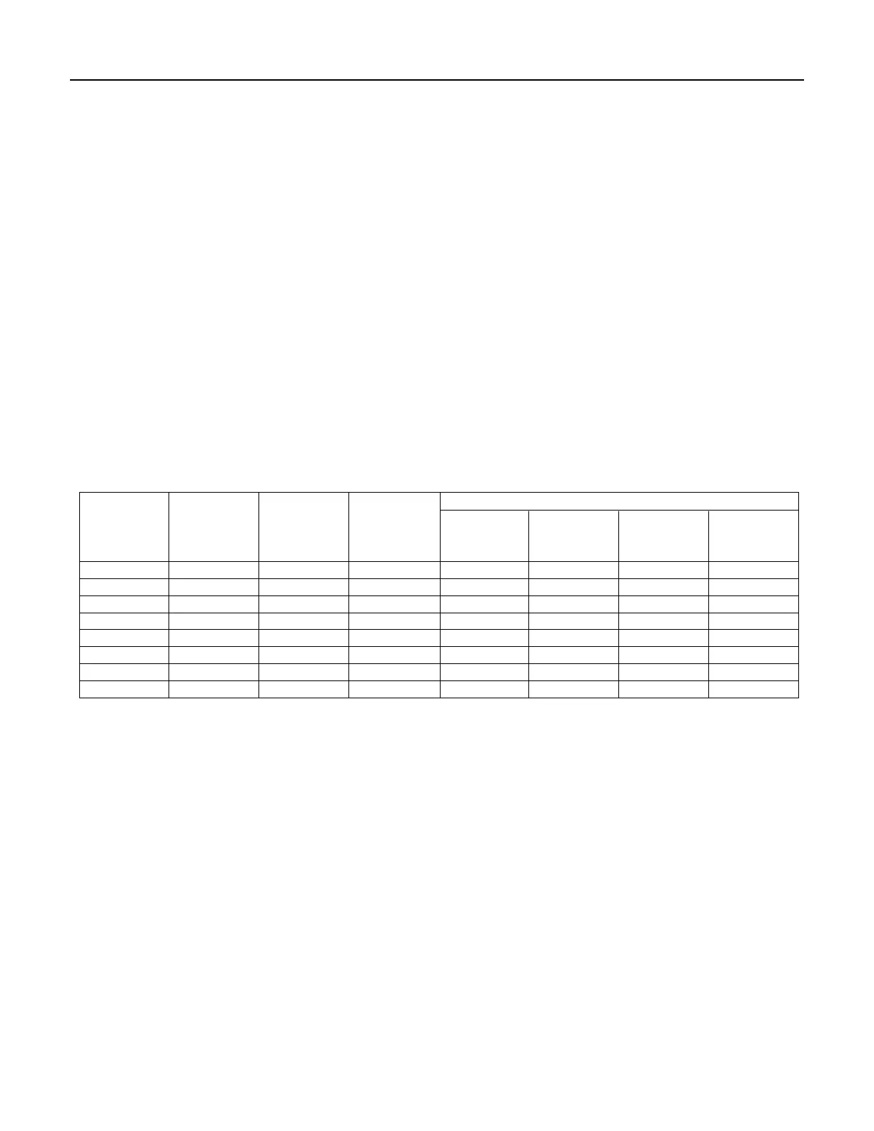
WIRING CHART – Recommended Wire and Fuse Sizes
BRANCH DISTANCE IN FEET FROM MOTOR TO METER
MAX.
FUSE*
0 51 101 201
MOTOR
VOLTS
LOAD
RATING
TO TO TO TO
HP
AMPS
AMPS
50 100 200 300
1/2 115 13.0 20 12 12 10 8
1/2 230 6.5 15 14 14 14 14
3/4 115 14.8 20 12 12 8 6
3/4 230 7.4 15 14 14 14 14
1 115 19.2 25 10 10 8 6
1 230 9.6 15 14 14 14 12
1-1/2 230 12.0 15 14 14 14 12
2 230 11.5 15 14 14 14 12
(*)Time delay fuse or circuit breakers are recommended in any motor circuit.
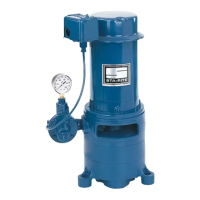
Step 1. Connect the ground wire first as shown in Figure
12. The ground wire must be a solid copper wire
at least as large as the power supply wires.
Step 2. There must be a solid metal connection between
the pressure switch and the motor for motor
grounding protection. If the pressure switch is
not connected to the motor, connect the green
ground screw in the switch to the green ground
screw under the motor end cover. Use a solid
copper wire at least as large as the power supply
wires.
Step 3. Connect the ground wire to a grounded lead in
a service panel, to a metal underground water
pipe, to a metal well casing at least ten feet (3M)
long, or to a ground electrode provided by the
power company or the hydro authority.
Step 4. Connect the power supply wires to the pressure
switch as shown in Figure 12.
Connection Procedure:
 Loading...