Locking torque 3 ÷ 4
- Fit the inlet manifold and lock the 2 screws to the
specified torque.
- Fit the carburettor onto the inlet manifold and lock
the clamp
N.B.
FIT THE CARBURETTOR THROUGH THE SUP-
PLEMENT ON THE MANIFOLD.
Locking torques (N*m)
Locking torque 11 ÷ 13
- Refit the cylinder head cover, tightening the 4
clamping screws to the prescribed torque.
- Refit the fan and the housing.
- Reassemble the oil pump control, the chain com-
partment cover, the by-pass and the oil sump as
described in the lubrication chapter.
- Reassemble the driving pulley, the belt and the
transmission cover as described in the transmis-
sion chapter.
Locking torques (N*m)
Locking torque 11 ÷ 13
Crankcase - crankshaft
- Precautionary remove the following units:
transmission cover, driving pulley, driven pulley
and belt, rear hub cover, gears, bearings and oil
seals as described in the transmission chapter.
- Remove the oil sump, the by-pass, the chain
compartment cover and the oil pump as in the lu-
brication chapter.
- Remove the flywheel cover, the fan, the flywheel
and the stator as described in the magneto fly-
wheel chapter.
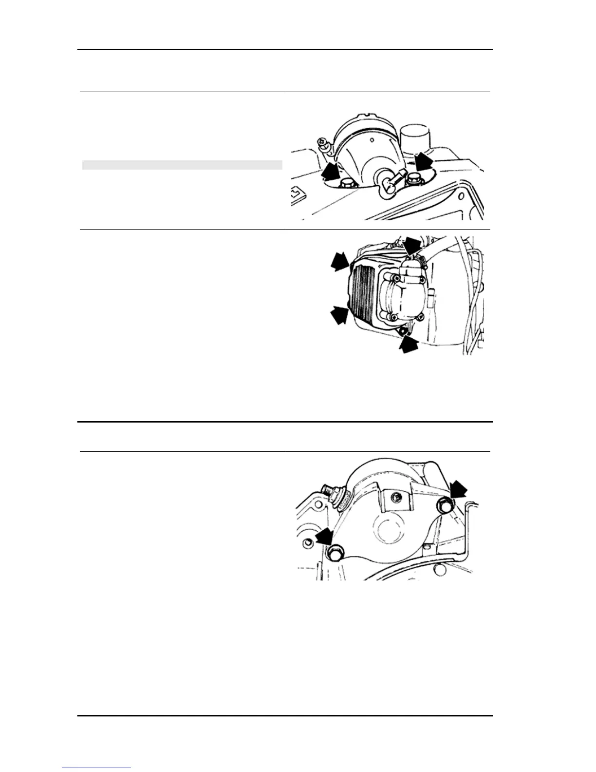
- Remove the oil filter and the oil pressure bulb.
- Remove the cylinder-piston-head unit as descri-
bed in the cylinder head timing system chapter.
- Remove the 2 retainers indicated in the figure
and the starter motor.
Engine Fly 125 - 150 4T
ENG - 122

 Loading...