1
<ARB7238>
IMPORTANT
FOR USE IN THE UNITED
KINGDOM
The wires in this mains lead are coloured in
accordance with the following code :
Blue :Neutral
Brown :Live
If the plug provided is unsuitable for your socket
outlets, the plug must be cut off and a suitable plug
fitted.
Do not connect either wire to the earth terminal of a
three pin plug.
NOTE
After replacing or changing a fuse, the fuse cover in the
plug must be replaced with a fuse cover which corre-
sponds to the colour of the insert in the base of the plug
or the word that is embossed on the base of the plug, and
the appliance must not be used without a fuse cover. If
lost, replacement fuse covers can be obtained from your
dealer.
Only 5 A fuses approved by B.S.I. or A.S.T.A. to B.S.
1362 should be used.
The cut-off plug should be disposed of and must not be
inserted into any 13 amp socket as this can result in electric
shock. The plug or adaptor or the distribution panel should be
provided with 5 amp fuse. As the colours of the wires in the
mains lead of this appliance may not correspond with coloured
markings identifying the terminals in your plug, proceed as
follows :
The wire which is coloured blue must be connected to the
terminal which is marked with the letter N or coloured black.
The wire which is coloured brown must be connected
to the terminal which is marked with the letter L or coloured
red.
The lightning flash with arrowhead symbol, within an
equilateral triangle, is intended to alert the user to the
presence of uninsulated "dangerous voltage" within the
product's enclosure that may be of sufficient magnitude to
constitute a risk of electric shock to persons.
RISK OF ELECTRIC SHOCK
DO NOT OPEN
CAUTION
IMPORTANT
CAUTION:
TO PREVENT THE RISK OF ELECTRIC SHOCK, DO NOT
REMOVE COVER (OR BACK). NO USER-SERVICEABLE
PARTS INSIDE. REFER SERVICING TO QUALIFIED
SERVICE PERSONNEL.
The exclamation point within an equilateral triangle is intended
to alert the user to the presence of important operating and
maintenance (servicing) instructions in the literature
accompanying the appliance.
This product complies with the Low Voltage Directive (73/23/
EEC), EMC Directives (89/336/EEC, 92/31/EEC) and CE Marking
Directive (93/68/EEC).
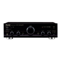
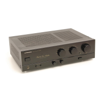
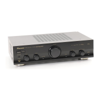
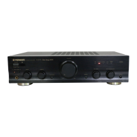
Thank you for buying this PIONEER product.
Please read through these operating instructions so you will know how to
operate your model properly. After you have finished reading the instruc-
tions, put them away in a safe place for future reference.
In some countries or regions, the shape of the power plug and power
outlet may sometimes differ from that shown in the explanatory draw-
ings. However, the method of connecting and operating the unit is the
same.
WARNING: TO PREVENT FIRE OR SHOCK HAZARD, DO
NOT EXPOSE THIS APPLIANCE TO RAIN OR MOISTURE.
STEREO AMPLIFIER
z¿.?/B
Î
STEREO AMPLIFIER
z¿.?/B Direct Energy MOS
STANDBY/ON
STANDBY
OFF ON
POWER
A SPEAKERS B BASS TREBLE
PHONES
LOUDNESS
MIN MAX
VOLUME
DIRECT/
SB MODE
BALANCE INPUT SELECTOR REC SELECTOR
CD TUNER PHONO
TAPE 2
MONITOR
CD TUNER
OFF SOURCE
L R
LINE/
SB
TAPE 1/
CD-R/MD
Î
+
2
7
3
1¡
4¢
7
3
_
+
STANDBY / ON
AMP CD TUNER TAPE
TAPE
SELECT
TAPE
DECK
I
DECK
II
CD
DISC
SELECT
STATION
TUNER
CD TUNER PHONO
TAPE 1 TAPE 2 LINE
VOLUME
STEREO AMPLIFIER
REMOTE CONTROL UNIT
[For European model]
If the socket outlets on the associated equipment are not suitable for the plug supplied with the product the plug must be removed
and appropriate one fitted.
The cut-off plug must be disposed of as an electrical shock hazard could exist if connected to a socket outlet.