25
A-607R
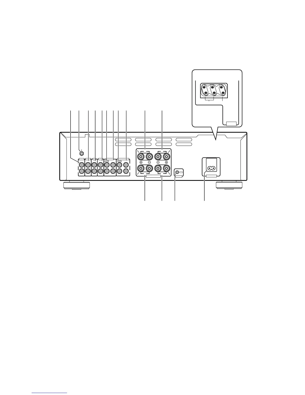
8. PANEL FACILITIES AND SPECIFICATIONS
8.1 REAR PANEL
0 SPEAKERS B terminals (Right channel)
- SPEAKERS B terminals (Left channel)
= AC INLET jack
Connect one end of the power cord to here and the other end to
an AC wall socket, or the AC outlet of an audio timer.
If you are going to be away from home for a long period of time,
disconnect the unit from the wall socket.
~ CONTROL OUT jack
This jack is for outputting control signals when operating other
components bearing the Î mark with the amplifier's remote con-
trol unit.
! SPEAKERS A terminals (Left channel)
@ SPEAKERS A terminals (Right channel)
# AC OUTLETS (European model only)
1 PHONO terminals
2 SIGNAL GND (Turntable ground) terminal
3 TUNER terminals
4 CD terminals
5 LINE terminals
6 TAPE 1/MD REC (OUT) terminals
7 TAPE 1/MD PLAY (IN) terminals
8 TAPE 2 MONITOR REC (OUT) terminals
9 TAPE 2 MONITOR PLAY (IN) terminals
@
=~
2345
6
78 9 0
-
!
#
Illustration shows U.K. model
1
GND
PHONO
IN IN IN IN INOUTINOUT
TUNER LINE
TAPE1/MD
TAPE2 MONITOR
CD
REC PLAY REC PLAY
L
R
L
R
R
R
L
L
B
A
SPEAKERS
CONTROL
OUT
AC INLET
SWITCHED
TOTAL 100W MAX
UNSWITCHED
100W MAX
AC
OUTLETS
European model only
 Loading...