3 4
FIG. 1
• Risk of electrical shock, connect only to a grounding type receptacle
protected by a ground fault circuit interrupter, (GFCI). Contact a
qualified electrician if you cannot verify that the receptacle is
protected by a GFCI.
NOTE - The Power Filter will be in four sections: a pump; filter assembly; hardware bag; and suction / return hoses.
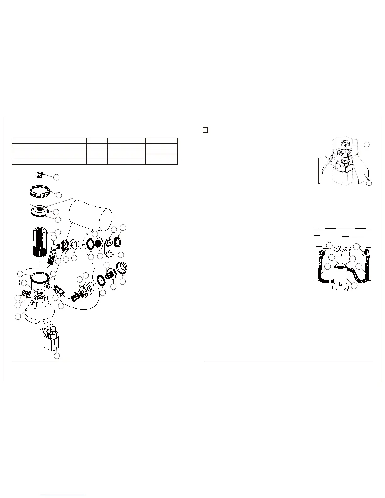
A. First, remove the Seal Top Retainer (10), Seal Top (9), and Filter Cartridge (15) from the assembled Filter Case.
Lubricate the pump O-ring with petroleum jelly. Hold the filter case (8) securely, and insert motor pump so that
the outlet on the volute housing extends out of the opening in the side of the filter case. Insert the motor pump
until the two ribs on the inlet of the volute housing protrude through the bottom of the filter case. Reach down
inside the filter case and place the Pump Retaining Nut (7) over the top of the volute housing inlet. Twist the Nut
(7) clockwise until it is snug. See Fig. 2.
B. Get the Suction and Return Hoses (12, 13), and remove two Hose
Clamps (14), from the hardware bag. Loosen the hose clamps and
slide them over one end of each hose. Lubricate O-rings (24) on the
Filter Case (8) and Volute Housing liberally with petroleum jelly.
Install one hose on the filter case suction inlet at the top, and one
hose on the filter case return outlet at the base. Tighten both of the
Hose Clamps (14).
C. Locate the Return Fitting assembly parts (21, 25-31). Lubricate the
(black) RF Gasket (26) liberally with petroleum jelly and install it over
the threads on the Return Fitting (25). Insert the Return Fitting (25)
with the RF Gasket (26) through the pool return fitting hole in the
wall from the inside of the pool, see Fig. 3 for correct location. Place
the (white) RF Thrust Washer (27) over the Return Fitting and then
thread the RF Nut (28) onto the fitting until it is hand tight. DO NOT
over tighten the RF Nut or wrinkle the pool wall around the RF Thrust
Washer (27) or the RF Gasket (26). Plug the pool’s Return Fitting (25) with the RF Plug (21) from the inside of the
pool. Set the RF Diverter Fitting (30) and RF Locking Ring (31) aside for later installation. Now locate the Pool
Suction Fitting assembly parts (16-20). Lubricate the (black) SF Gasket (17) liberally with petroleum jelly and
install it over the threads on the Suction Fitting (16). Insert the Suction Fitting (16) with SF Gasket (17) through
the pool suction fitting hole in the wall from the inside of the pool. Place the (white) SF Thrust Washer (18) over
the Suction Fitting and then thread the SF Nut (19) onto the fitting until it is hand tight. DO NOT over tighten
the SF Nut or wrinkle the pool wall around the SF Thrust Washer (18) or the SF Gasket (17). Cap the pool’s
Suction Fitting (16) with the SF Water Cap (20). Only hand tighten the Water Cap (20). Start filling pool.
D. After the pool is filled, position the Filter Assembly between the two fittings on the side of the pool, about 6
inches out from the base. The suction hose (12), coming from the top of the filter case should be facing the right,
and the return hose (13) coming from the pump, on the lower side of the case, should be facing the left; see Fig.3.
FIG. 3
POOL
RETURN
FITTING
POOL
SUCTION
FITTING
14
14
11
13 12
9
8
Should you encounter any problems, contact the Customer Service at (888) 919-0070.
Extended operating days and hours during peak season requirements.
Should you encounter any problems, contact the Customer Service at (888) 919-0070.
Extended operating days and hours during peak season requirements.
4. The RP Type pump/filter systems are manufactured by Polygroup and ETL control number 4000608 - double
insulated and grounded - 115 V.A.C. - 60 Hz. (ALL Units must have a minimum of 105 V.A.C. to start and run
properly.)
RP600 Filter System with F600C Pump
RP800 Filter System with F700C Pump
RP1000 Filter System with F1000C Pump
RP1000 Filter System with F1500C Pump
RP2000 Filter System with F2000C Pump
46 watts
57 watts
80 watts
120 watts
210 watts
0.8 amps
1.1 amps
2.2 amps
2.2 amps
2.2 amps
580 G.P.H.
780 G.P.H.
1075 G.P.H.
1500 G.P.H.
2000 G.P.H.
THE FILTER CARTRIDGE (15) WILL HOLD 1”
DIAMETER CHLORINE TABLETS. CHECK
YOUR CHLORINE LEVELS TO DETERMINE
THE PROPER NUMBER OF TABLETS TO ADD.
LIBERALLY
LUBRICATE
THE O-RINGS
(17,22,23,24 &26)
WITH SOME
PETROLEUM
JELLY
PATENTED
FILTER
CARTRIDGE
SYSTEM #7,005,062
KEY DESCRIPTION
1-6 MOTOR PUMP
7 PUMP RETAINING NUT
8 FILTER CASE
9 SEAL TOP
10 SEAL TOP RETAINER
11 VENT SCREW
12 SUCTION HOSE
13 RETURN HOSE
14 HOSE CLAMPS
15 FILTER CARTRIDGE
16 SUCTION FITTING (SF)
17 SF GASKET (Black)
18 SF THRUST WASHER (White)
19 SF NUT
20 SF WATER CAP (Use for service only)
21 RF PLUG (Use for service only)
22 O-RING (On Filter Case)
23 O-RING (On Vent Screw)
24 O-RING (On Hose Connections)
25 RETURN FITTING (RF)
26 RF GASKET (Black)
27 RF THRUST WASHER (White)
28 RF NUT
29 RF ELBOW 90°
30 RF DIVERTER FITTING
31 RF LOCKING RING
32 POOL WALL
11
10
23
9
15
29
24
22
7
13
14
4 Ea.
4 Ea.
8
12
14
24
19
18
16
20
17
1-6
28
27
26
25
24
21
30
31
32
]Volute Housing
Pump System Wattage Amperage Flow Rate
*GPH - Gallons Per Hour
FIG. 2
7
8
Volute
Housing
Outlet
Motor Pump
Volute
Housing
Inlet
1 POWER FILTER INSTALLATION: (Reference Page 3, Fig. 1)
WARNING - EXTREMELY IMPORTANT!
• Receptacle must be at least 10 feet away from pool.
• Filter system can be used as many hours as desired.
• Do not use an extension cord to connect unit to electric
supply; provide a properly located outlet.
• Do not bury the cord.
 Loading...