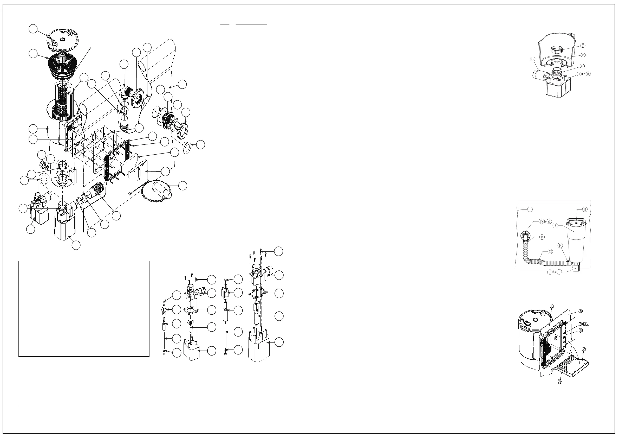
1. POWER FILTER INSTALLATION: (REFERENCE PAGE 3, FIG. 1)
WARNING - EXTREMELY IMPORTANT!
3
4
4
3
11
10
8
22
28
29
7
30
6
1-6
1-6
12
14
13
27
26
25
30
21
20
15
16
32
17
18
19
12
14
9
24
23
22
THE FILTER CARTRIDGE (9) WILL HOLD 1”
DIAMETER CHLORINE TABLETS. CHECK
YOUR CHLORINE LEVELS TO DETERMINE
THE PROPER NUMBER OF TABLETS
TO ADD.
YOU MUST
HAVE THIS
TYPE OF
FILTER WITH
A CENTRAL
CORE MESH
DIVIDER
TO USE THE
CHLORINE
DISPENSER.
US PATENT
# 7,005,062
PATENT
PENDING
FILTER
SYSTEM
NOTE:
Install Service
Plugs (30)
only when
servicing
system!
KEY DESCRIPTION
1 PUMP BODY W/CORD
2 ROTOR ASSEMBLY
2A MAGNET AXLE
2B IMPELLER
2C SHAFT
2D THRUST WASHERS
2E SHAFT END CAPS
3 PUMP GASKET
4 VOLUTE HOUSING
5 PHILLIPS HEAD SCREWS
6 O-RING
7 PUMP RETAINING NUT
8 SKIMMER CANISTER
9 FILTER CARTRIDGE
10 STRAINER BASKET
11 LOCK TOP
12 O-RING
13 RETURN HOSE
14 HOSE CLAMP
15 POOL WALL FITTING
16 GASKET
17 THRUST WASHER
18 NUT
19 ELBOW 90°
20 DIVERTER FITTING
21 LOCKING RING
22 GASKET
23 FACE PLATE
24 HEX HEAD SCREWS
25 WEIR FOAM
26 WEIR
27 VACUUM ADAPTER
28 DRAIN CAP
29 SEAL GASKET
30 SERVICE PLUGS
32 POOL WALL
IMPORTANT! Your pump is protected by a thermal
overload. This device senses the temperature of the
pump and if it is getting too hot, it will open the
electric circuit and the pump will stop running until it
cools off some. It will automatically turn back on
when it has cooled down enough. This is a safety
device to help prevent excessive pump damage. If
your pump is doing this, it is because of high pool
water temperature and/or high air temperature
and/or low water flow thru the pump. If this happens
you need to check water flow thru the filter and
correct it if needed. This pump uses the water flow
for cooling. You may also want to run the pump at
night when the temperature is lower.
Should you encounter any problems, contact the Customer Service at (888) 919-0070 from 8 AM to 5 PM Mon. thru Fri.
EST. Extended operating days and hours during peak season requirements.
2E
2B
2A
2C
2D
1
2
3
4
5
2E
2B
2C
2D
1
2
3
4
5
6 EA.
2 EA.
2 EA.
2 EA.
2 EA.
4 EA.
2A
F600C & F700C
F1000C / F1500C / F2000C
FIG.1
• Risk of electrical shock, connect only to a grounding type
receptacle
• Receptacle must be at least 10 feet away from pool.
• Filter system can be used as many hours as desired, but NEVER
when the pool is occupied.
• Do not use an extension cord to connect unit to electric
supply; provide a properly located outlet.
• Do not bury the cord.
NOTE - The Power Filter will be in four sections: a pump; filter assembly; hardware bag; and return hose.
A. First, Locate the filter assembly, remove the Lock Top (11), Strainer Basket (10), and Filter Cartridge (9) from
the assembled Filter Case. Locate the mounting location for the power filter on the Pool Wall
(32). Install one Gasket (22) over the four alignment pins on the skimmer canister (8) and place it up to the
outside pool wall inserting the four alignment pins through the four large holes in pool wall. Now leaning
against the Skimmer to hold it in place add the inside gasket (22) over the pins on the inside of the pool
wall. Now place the Face Plate (23) over the alignment pins. Place the Hex Head Screws (24) into their holes.
Start all the Hex Head Screws one and a half turns each. Then proceed in tightening them in equal turns
each in sequence around the Face Plate until all are equally tight and you have a
good even seal. Warning! Be sure not to over tighten them, you just need a water tight seal.
B. Now lubricate the pump O-ring (6) with petroleum jelly (not provided). Hold the Skimmer Canister (8)
securely, and insert pump assembly (1-6) so that the outlet on the Volute Housing (4) extends out to
the side of the canister as shown in Fig. 2. Insert the pump until it bottoms out, and the two ribs on the
volute housing insert into the two slots on the bottom of the canister. Reach down inside the canister and
place the Pump Retaining Nut (7) over the top of the volute housing
inlet as shown in Fig. 2. Twist the Nut (7) clockwise until it is snug.
C. Locate the Pool Wall Fitting assembly parts (15-21). Lubricate the black
Wall Fitting Gasket (16) with petroleum jelly and install it over the
threads on the Pool Wall Fitting (15). Insert the pool wall fitting with
the gasket through the hole in the wall from the inside of the pool.
Place the Thrust Washer (17) over the pool wall fitting and then
thread the Wall Fitting Nut (18) onto the fitting until it is hand tight.
DO NOT over tighten the wall fitting nut or wrinkle the pool wall
around the Wall Fitting Thrust Washer (17) or Wall Fitting Gasket (16).
Now apply some petroleum jelly to the thread of the Elbow 90° (19)
and install the elbow into the wall fitting assembly. Install the Diverter
Fitting (20) and Locking Ring (21) onto the wall fitting.
D. Get the Return Hose (13) and remove the two Hose Clamps (14) from the hardware bag. Loosen the hose
clamps and slide them over the end of the hose. It is recommended to lubricate the O-Rings (12) on the
Volute Housing (4) and on the Elbow (19) before installing the hose (13). Install the hose on the pump volute
housing and on the Elbow (19). Tighten both of the Hose Clamps (14). See Fig. 3.
E. Place the Filter Cartridge (9) and the Strainer Basket (10) back into the
Skimmer Canister (8). It is important that the Filter Cartridge (9) slips
over the Pump Retaining Nut (7) and seals at the bottom of the canister
so that the Strainer Basket (10) will seat in it’s groove inside the canister.
See Fig. 4. Place the Lock Top (11) on top of the Skimmer Canister (8)
and lock it in place by turning it clockwise until it is locked. Push the
Weir Foam Pad (25) into the Weir (26) and under the tabs, to hold it in
place. Take the Weir (26) and slide it into the grooves from inside the
pool. See Fig. 4. Once the weir is pushed inside the grooves, flip it over
as shown by the Arrow #2 in Fig. 4, to lock it in place. NOTE: The weir
can ONLY be pushed into the grooves as shown by Arrows #1 in Fig. 4,
by holding it horizontal. Be sure the weir moves freely through the
opening, if not carefully trim away any obstructing material to allow the weir to move freely.
F. After the pool is filled, SEE (WATER LEVEL FIG. 4) check the hose connections and fittings to make sure there
is no water leakage. If any leaks are found, see #4 in the Trouble Shooting guide on page #8.
FIG. 4
MIN. WATER
LEVEL
MAX. WATER
LEVEL
FIG.3
32
6
FIG.2
NOTE:
When Pump (1) needs servicing or working on Return Hose (13), turn off power and install the Service
Plug (30) into Pool Wall Fitting (15) after removing Locking Ring (21) and Diverter Fitting (20). Also install a
Service Plug (30) into center hole of the Skimmer Canister (8) after removing the Pump Retaining Nut (7).
See FIG. 1. When service is complete remove both Service Plugs (30) reversing the procedures above.
 Loading...