CPS20 Series: Power Supply Instruction Manual
CPS20 Serie: Bedienungsanleitung für Stromversorgung
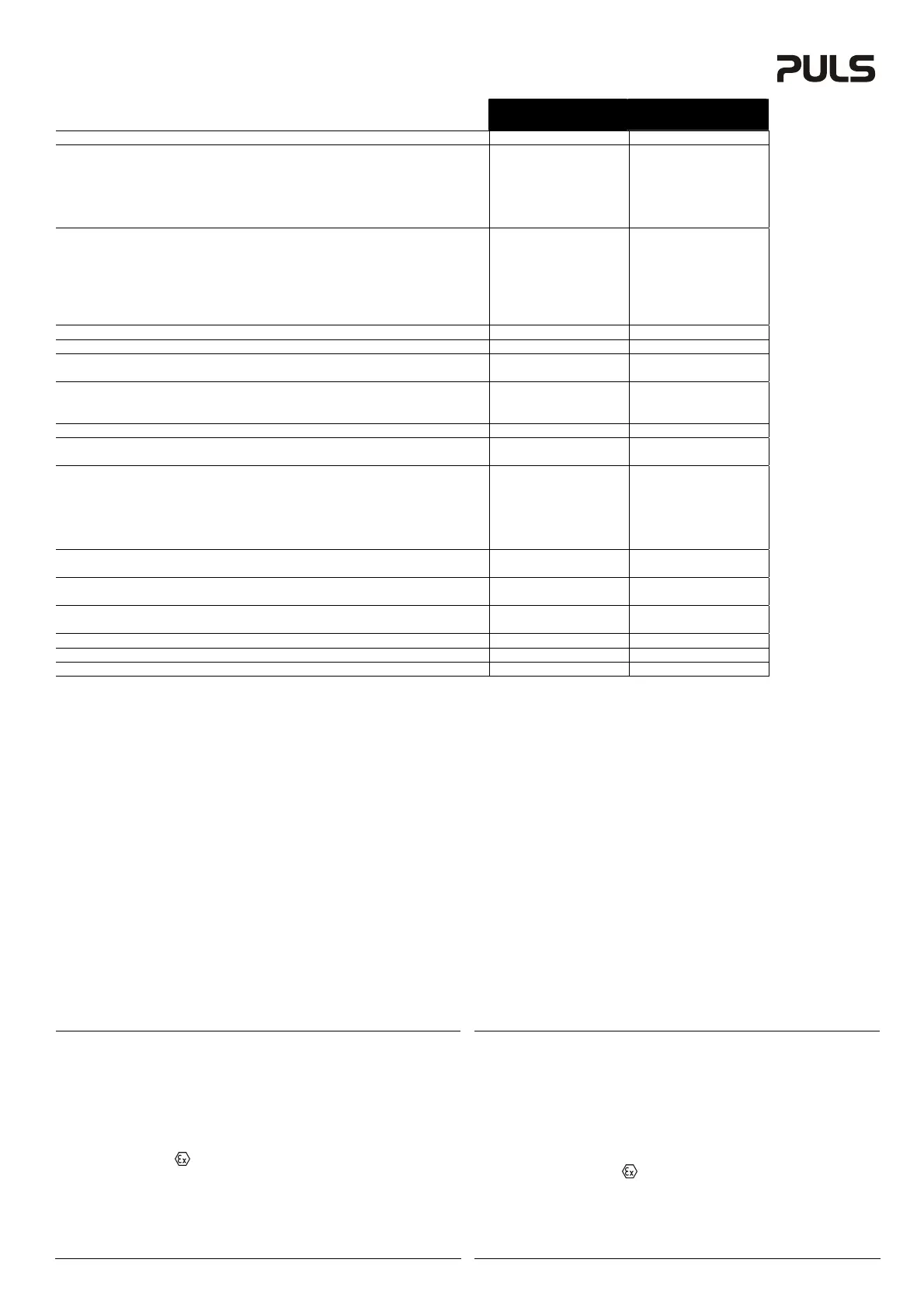
Technical Data
1)
Technische Daten
1)
CPS20.241
CPS20.241-A1
15)
CPS20.481
Output Voltage Ausgangsspannung nom. DC 24-28V DC 48-56V
Factory Setting at Full Load Werkseinstellung bei Nennlast typ. 24.1V 48.0V
Output Current Ausgangsstrom nom. 20A at 24V, 17.1A at 28V 10A at 48V, 8.6A at 56V
PowerBoost
11)
24A at 24V, 20.6A at 28V 12A at 48V, 10.3A at 56V
Output Power Ausgangsleistung nom. 480W 480W
PowerBoost
11)
576W 576W
Output Ripple & Noise Voltage
2)
Ausgangswelligkeit
2)
max. 50mVpp 50mVpp
AC Input Voltage AC Eingangsspannung nom. AC 100-240V -15%/+10%
18)
AC 100-240V -15%/+10%
18)
Input Frequency Eingangsfrequenz nom. 50-60Hz 50-60Hz
AC Input Current
3)
AC Eingangsstrom
3)
typ. 4.36A / 2.33A 4.36A / 2.33A
Power Factor
3)
Leistungsfaktor
3)
typ. 0.99 / 0.95 0.99 / 0.95
Allowed Voltage L or N to Earth Erlaubte Spannung L oder N zu Erde max. 264Vac 264Vac
PFC-Norm EN 61000-3-2 PFC-Norm EN 61000-3-2 - Yes / Ja Yes / Ja
DC Input Voltage DC Eingangsspannung nom. - -
Input Inrush Current
4)
Einschaltspitzenstrom
4)
typ. 9A / 7A 9A / 7A
Hold-up Time
3)
Pufferzeit
3)
typ. 26ms / 26ms 26ms / 26ms
Efficiency
3)
Wirkungsgrad
3)
typ. 92.7% / 94.0% 92.6% / 93.9%
Power Losses
3)
Verlustleistung
3)
typ. 37.8W / 30.6W 38.4W / 31.2W
Operational Temperature Range Betriebstemperaturbereich nom. -25°C - +70°C -25°C - +70°C
Output Derating Leistungsrücknahme +60°C to +70°C 12W/°C 12W/°C
Storage Temperature Range Lagertemperaturbereich nom. -40°C - +85°C -40°C - +85°C
Humidity
5)
Feuchte
5)
IEC 60068-2-30 5 - 95% r.H. 5 - 95% r.H.
Vibration Schwingen IEC 60068-2-6 2g 2g
Shock Schocken IEC 60068-2-27 30g 6ms, 20g 11ms 30g 6ms, 20g 11ms
Degree of Pollution (non-conductive) Verschmutzungsgrad (nicht leitend) EN 50178, IEC 62103 2 2
Degree of Protection Schutzart EN 60529 IP20 IP20
Class of Protection Schutzklasse IEC 61140 I
6)
I
6)
Over-temperature Protection Übertemperaturschutz OTP Yes / Ja Yes / Ja
Output Over-voltage Protection Überspannungsschutz am Ausgang OVP, max. 32Vdc 60Vdc
Return Voltage Resistance
8)
Rückspeisefestigkeit
8)
max. 35Vdc 63Vdc
Leakage Current
7)
TN/TT-mains PE- Ableitstrom
7)
TN/TT- Netze max. 0.55mA / 0.96mA 0.55mA / 0.96mA
IT-mains IT- Netze max. 1.31mA / 2.09mA 1.31mA / 2.09mA
Parallel Use Parallelschaltbar - Yes / Ja
13)
Yes / Ja
13)
Serial Use
12)
Serienschaltbar
12)
- Yes / Ja
13)
Yes / Ja
13)
Dimensions
9)
(WxHxD) Abmessungen
9)
(BxHxT) nom. 65x124x127mm 65x124x127mm
Weight Gewicht max. 1000g / 2.2lb 1000g / 2.2lb
DC-OK Signal DC-OK Signal - Yes / Ja
16)
Yes / Ja
16)
Approvals Zulassungen - Æ 10) Æ 10)
Limited Warranty Gewährleistung Years / Jahre 3 3
1) All parameters are specified at 230Vac input voltage, TN- TT- IT-mains, nominal output
current, 25°C ambient and after a 5 minutes run-in time unless otherwise noted.
2) 50-Ohm measurement, bandwidth 20MHz
3) at 120Vac, 60Hz and/ or 230Vac 50Hz
4) Peak value at 120Vac and/ or 230Vac, at an ambient temperature of 40°C and cold start.
5) Do not energize while condensation is present.
6) PE connection required (Ground)
7) Leakage current at 132Vac, 60Hz and/ or 264Vac, 50Hz
8) Loads such as decelerating motors and inductors can feed voltage back to the output of the
power supply. The figure represents the maximum allowed feed back voltage
9) Depth without DIN-rail
10) See data sheet or markings on the unit.
11) The PowerBoost is continuously allowed up to an ambient temperature of 45°C. Do not use
the PowerBoost longer than a duty cycle of 10% and/ or not longer than max. 1 minute every
10 minutes.
12) Use only power supplies of the same type. The total output voltage should not be >150Vdc.
13) Set unit in “Parallel Use” mode by changing the jumper position on the front. In order to
achieve a sharing of the load current between the individual power supplies, the “Parallel Use”
mode regulates the output voltage in such a manner, that the voltage at no load is approx. 5%
higher than at nominal load. A fuse or diode on the output of each unit is required if more than
three units are connected in parallel. It might be necessary to cycle the input power (turn-off
for at least five seconds), if the output was in Hiccup
PLUS
mode due to overload or short
circuits and the required output current is higher than the current of one unit.
14) No current share between the units. Allowed up to 45°C ambient temperature. A fuse or diode
on the output of each unit is required if more than three units are connected in parallel.
15) Version with ATEX approval and conformal coated PC-board
16) Relay contact: 60Vdc 0.3A; 30Vdc 1A; 30Vac 0.5A
17) Open collector transistor output, max. 30mA
18) Below 100Vac, an output derating might be required. See figure 6
1) Alle Werte gelten bei 230Vac, TN- TT- IT-Netze, Nennausgangsstrom, 25°C Umgebung und
nach einer Aufwärmzeit von 5 Minuten, wenn nichts anderes angegeben ist.
2) 50-Ohm Messung, Bandbreite 20MHz
3) bei 120Vac, 60Hz und/ oder 230Vac, 50Hz
4) Spitzenstrom bei 120Vac und/ oder 230Vac, einer Umgebungstemperatur von 40°C und
Kaltstart.
5) Nicht betreiben, solange das Gerät Kondensation aufweist.
6) PE Verbindung erforderlich.
7) Ableitstrom bei 132Vac, 60Hz und/ oder 264Vac, 50Hz
8) Bremsende Motoren oder Induktivitäten können Spannung zum Ausgang des Netzteils
rückspeisen. Der Wert gibt die max. zulässige Rückspeisespannung an.
9) Tiefe ohne DIN-Schiene
10) Siehe Datenblatt oder Prüfzeichen auf dem Gerät.
11) Der PowerBoost ist bis zu einer Umgebungstemperatur von +45°C dauerhaft erlaubt. Darüber
soll sie nicht länger als 10% (<1 Minute alle 10 Minuten) entnommen werden.
12) Nur gleiche Geräte bis zu einer Gesamtspannung von 150Vdc
13) Gerät mit Jumper an der Front auf „Parallel Use“ umstellen. Im „Parallel Use“ Modus wird
durch eine stromabhängige Ausgangsspannung eine Stromaufteilung zwischen den einzelnen
Geräten erreicht. Im Leerlauf ist dabei die Ausgangsspannung ca. 5% höher als bei Nennlast.
Eine Sicherung oder Diode am Ausgang ist erforderlich wenn mehr als 3 Geräte parallel
geschaltet werden. Nach einer Überlastung, in der das Gerät in den Hiccup
PLUS
Modus
gegangen ist, kann ein Aus und Einschalten der Netzspannung erforderlich sein, wenn der
Strombedarf höher als der eines einzelnen Geräts ist.
14) Keine Stromaufteilung zwischen den Geräten. Erlaubt bis max. 45°C. Eine Sicherung oder
Diode je Ausgang ist erforderlich wenn mehr als 3 Geräte parallel geschaltet werden.
15) Version mit ATEX Zulassung und schutzlackierte Leiterplatte
16) Relaiskontakt: 60Vdc 0,3A; 30Vdc 1A; 30Vac 0,5A
17) Open-Kollektor Transistorausgang, max. 30mA
18) Unterhalb 100Vac kann eine Leistungsrücknahme erforderlich sein. Siehe Bild 6.
Installation
Use DIN-rails according to EN 60715 or EN 50022 with a height of 7.5 or 15mm. Mounting
orientation must be terminals on the bottom. For other orientations see data sheet. Do not obstruct
air flow as the unit is convection cooled. Ventilation grid must be kept free of any obstructions. The
following installation clearances must be kept when power supplies are permanently fully loaded:
Left / right: 0mm (or 15mm in case the adjacent device is a heat source)
40mm on top, 20mm on the bottom of the unit.
Use in hazardous location areas
Units which are marked with "Class I Div 2" are suitable for use in Class I Division 2 Groups A, B,
C, D locations.
Units which are marked with II 3G EX nA nC IIC T3 Gc are suitable for use in Group II
Category 3 (Zone 2) environments and are evaluated according to EN 60079-0:2009 and EN
60079-15:2010.
WARNING EXPLOSION HAZARDS!
Substitution of components may impair suitability for this environment. Do not disconnect the unit
or operate the voltage adjustment or S/P jumper unless power has been switched off or the area
is known to be non-hazardous. A suitable enclosure must be provided for the end product which
has a minimum protection of IP54 and fulfils the requirements of the EN 60079-15:2010.
Installation
Geeignet für DIN-Schienen entsprechend EN 60715 oder EN 50022 mit einer Höhe von 7,5 oder
15mm. Der Einbau hat so zu erfolgen, dass sich die Anschlussklemmen unten befinden. Für
andere Einbaulagen siehe Datenblatt. Luftzirkulation nicht behindern! Das Gerät ist für
Konvektionskühlung ausgelegt. Es ist für ungehinderte Luftzirkulation zu sorgen. Folgende
Einbauabstände sind bei dauerhafter Volllast einzuhalten:
Links / rechts: 0mm (oder 15mm bei benachbarten Wärmequellen)
Oben: 40mm, unten 20mm vom Gerät.
Betrieb in explosionsgefährdeter Umgebung
Geräte, die mit "Class I Div 2" gekennzeichnet sind, sind für den Einsatz in Klasse I Division 2
Gruppen A,B,C,D Umgebung geeignet.
Geräte, welche die Kennzeichnung II 3G EX nA nC IIC T3 Gc tragen, sind nach EN 60079-
0:2009 und EN 60079-15:2010 getestet und können in Gruppe II, Kategorie 3 (Zone 2)
Umgebungen verwendet werden.
ACHTUNG EXPLOSIONSGEFAHR! Veränderungen am Gerät können die Tauglichkeit für diese
Umgebung beeinträchtigen. Anschlüsse nicht abklemmen, S/P-Jumper und Spannungseinstellung
nicht verändern, solange Spannung anliegt oder die Umgebung als explosionsgefährlich gilt. Das
Gerät muss mindestens in ein IP54 Gehäuse, welches den Anforderungen der EN 60079-15:2010
entspricht, eingebaut werden.
 Loading...