EN
QS40.241, QS40.241-C2 Installation Manual
Product Description
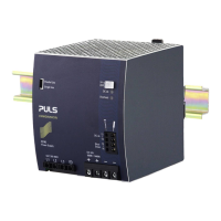
The QS40.241 is a DIN-rail mountable single-phase-input power supply, which provides a floating,
stabilized and galvanically separated SELV/PELV output voltage.
The QS40.241-C2 device is the same as the QS40.241 but with partially conformal coated pc-boards.
Intended Use
This device is designed for installation in an enclosure and is intended for commercial use, such as in
industrial control, process control, monitoring and measurement equipment or the like.
Do not use this device in equipment, where malfunctioning may cause severe personal injury or
threaten human life without additional appropriate safety devices, that are suited for the end-
application.
If this device is used in a manner outside of its specification, the protection provided by the device may
be impaired.
Installation Instructions
Install device in an enclosure providing protection against electrical, mechanical and fire hazards.
Install the device onto a DIN-rail according to EN 60715 with the input terminals on the bottom of the
device. Other mounting orientations require a reduction in output current.
Make sure that the wiring is correct by following all local and national codes. Use appropriate copper
cables that are designed for a minimum operating temperature of 60°C for ambient temperatures up to
+45°C, 75°C for ambient temperatures up to +60°C and 90°C for ambient temperatures up to +70°C.
Ensure that all strands of a stranded wire enter the terminal connection. Unused screw terminals
should be securely tightened. Use ferrules for wires on the input terminals.
The device is designed for pollution degree 2 areas in controlled environments. No condensation or
frost is allowed.
The enclosure of the device provides a degree of protection of IP20. The enclosure does not provide
protection against spilled liquids.
The device is designed for overvoltage category II zones.
The device is designed as “Class of Protection I” equipment according to IEC 61140. Do not use
without a proper PE (Protective Earth) connection.
The device is suitable to be supplied from TN, TT or IT mains networks. The continuous voltage
between the input terminal and the PE potential must not exceed 276Vac.
A disconnecting means shall be provided for the input of the device.
The device is designed for convection cooling and does not require an external fan. Do not obstruct
airflow and do not cover ventilation grid!
The device is designed for altitudes up to 4000m (13125ft). Above 2000m (6560ft) a reduction in
output current is required.
Keep the following minimum installation clearances: 40mm on top, 20mm on the bottom, 5mm left and
right side. Increase the 5mm to 15mm in case the adjacent device is a heat source. When the device
is permanently loaded with less than 50%, the 5mm can be reduced to zero.
The device is designed, tested and approved for branch circuits up to 30A (UL) and 32A (IEC) without
additional protection device. If an external fuse is utilized, do not use circuit breakers smaller than 16A
B- or C-Characteristic to avoid a nuisance tripping of the circuit breaker.
The maximum surrounding air temperature is +70°C (+158°F). The operational temperature is the
same as the ambient or surrounding air temperature and is defined 2cm below the device.
The device is designed to operate in areas between 5% and 95% relative humidity.
Installation Instructions for Hazardous Location Areas
The device is suitable for use in Class I Division 2 Groups A, B, C, D locations and for use in Group II
Category 3 (Zone 2) environments.
Classification: ATEX: EPS 14 ATEX 1 638 X, II 3G EX ec nC IIC T3 Gc / IECEx EPS 14.0007X
WARNING EXPLOSION HAZARDS!
Substitution of components may impair suitability for this environment.
Do not disconnect the device, operate the voltage adjustment or the S/P jumper unless power has
been switched off or the area is known to be non-hazardous.
A suitable enclosure must be provided for the end product which has a minimum protection of IP54
and fulfils the requirements of the EN 60079-0.
Functional Description
The output is electronically protected against no-load, overload and short circuit and can supply any
kind of loads, including unlimited inductive or capacitive loads. If capacitors with a capacitance >4.5F
are connected, the unit might charge the capacitor in an intermittent mode.
Do not apply return voltages from the load to the output terminals higher than 35V.
The output voltage can be adjusted with a small flat-blade screwdriver behind the flap on the front.
The DC OK LED reports an output voltage above 90% of the adjusted voltage of a running device.
The DC OK relay monitors the output voltage and the contact is closed when the DC OK LED is on.
Contact ratings: 60Vdc 0.3A, 30Vdc 1A, 30Vac 0.5A for resistive loads.
The red overload LED is on when the output voltage falls below 90% of the adjusted value. The LED is
flashing, when the device is in overload or short circuit mode or has switched off due to over-
temperature or when the “Remote OFF” signal is activated. Input voltage is required.
The device is equipped with an over-temperature protection. In case of a high temperature, the output
shuts down and starts automatically again after cooling off.
At heavy overloads (when output voltage falls below 20V), the device delivers continuous output
current for 2 to 4s (depending on the overload). After this, the output is switched off for approximately
17s before a new start attempt is automatically performed. This cycle is repeated as long as the
overload exists.
Devices can be paralleled to increase the output power. The ambient temperature is not allowed to
exceed +60°C. The output voltage of all devices shall be adjusted to the same value (±100mV) in
“Single Use” mode with the same load conditions on all units, or the units can be left with the factory
settings. After the adjustments, set the unit to “Parallel Use” mode, in order to achieve load sharing.
The “Parallel Use” mode regulates the output voltage in such a manner that the voltage at no load is
approx. 4% higher than at nominal load. Energize all units at the same time. It also might be
necessary to cycle the input power (turn-off for at least five seconds), if the output was in overload or
short circuit. If more than three devices are connected in parallel, a diode, fuse or circuit breaker with a
rating of 50 or 63A is required on each output.
Same devices can be connected in series for higher output voltages. It is allowed to connect as many
devices in series as needed, providing the sum of the output voltage does not exceed 150Vdc.
In case of an internal defect, a redundant circuit limits the maximum output voltage to 32V. The output
shuts down and automatically attempts to restart.
The device is equipped with a remote ON/OFF function to turn the output off. For this connect pin 15
with pin 16.
The output voltage can be remotely adjusted between 22 and 28Vdc by applying a control voltage
between pin 15 and the (-) terminal. See product datasheet for details.
Technical Data
All values are typical figures specified at 230Vac 50Hz input voltage, 24V,
40A output load, 25°C ambient temperature and after a 5 minutes run-in
time unless otherwise noted.
Output voltage DC 24V Nominal
Adjustment range 24 – 28Vdc Factory setting 24.1V
Output current Continuous:
40 – 34.3A Below +60°C ambient
30 – 25.7A At +70°C ambient
Short-term, up to 4s:
60 – 51.5A Below +70°C ambient
Derate linearly between +60°C and +70°C
Input voltage AC AC 100 - 240V -15% / +10%
Mains frequency 50 – 60Hz ±6%
Input current AC 8.6 / 4.5A At 120 / 230Vac
Power factor 0.99 / 0.99 At 120 / 230Vac
Input inrush current 17 / 11A pk At 120 / 230Vac, temp.
independent
Efficiency 93.6 / 94.6% At 120 / 230Vac
Power losses 65.6 / 54.8W At 120 / 230Vac
Hold-up time 27 / 27ms At 120 / 230Vac
Temperature range -25 to +70°C
Max. wire size (litz wire) 4mm² For input terminals
Wire size AWG AWG 20-10 For input terminals
Max. wire diameter 2.8mm For input terminals
Wire stripping length 7mm / 0.28inch For input terminals
Tightening torque 1Nm / 9lb.inch For input terminals
Max. wire size (litz wire) 10mm² For output terminals
Wire size AWG AWG 22-8 For output terminals
Max. wire diameter 5.2mm For output terminals
Wire stripping length 12mm / 0.5inch For output terminals
Tightening torque 2.3Nm / 20lb.inch For output terminals
Max. wire size (litz wire) 1.5mm² For signal terminals
Wire size AWG AWG 26-14 For signal terminals
Max. wire diameter 1.5mm For signal terminals
Wire stripping length 7mm / 0.28inch For signal terminals
Size (wxhxd) 125x124x127mm Without DIN-rail
Weight 1900g / 4.2lb
Functional Diagram
+
+
-
-
Output
Over-
Voltage
Protection
Bridgeless
PFC
Converter
Voltage
Regulator
Power
Converter
Output
Filter
Output
Power
Manager
Temper-
ature
Shut-
down
Input Fuse
Input Filter
Inrush Current
Limiter
V
OUT
L
N
DC-OK
Contact
DC-OK
LED
DC-ok
Relay
13
14
Overload
LED
Single /
Parallel
Event Datalogger
ON/OFF,
Voltage
Control
15
16
Remote ON/OFF
Voltage control
Output Characteristic
Output voltage
70A
24V
Output current
12V
0V
10A 30A 40A 50A0A
Adjustment range
28V
A
B
20A 60A
C
20V
A: continuous current
B: intermittent current
C: up to 4s
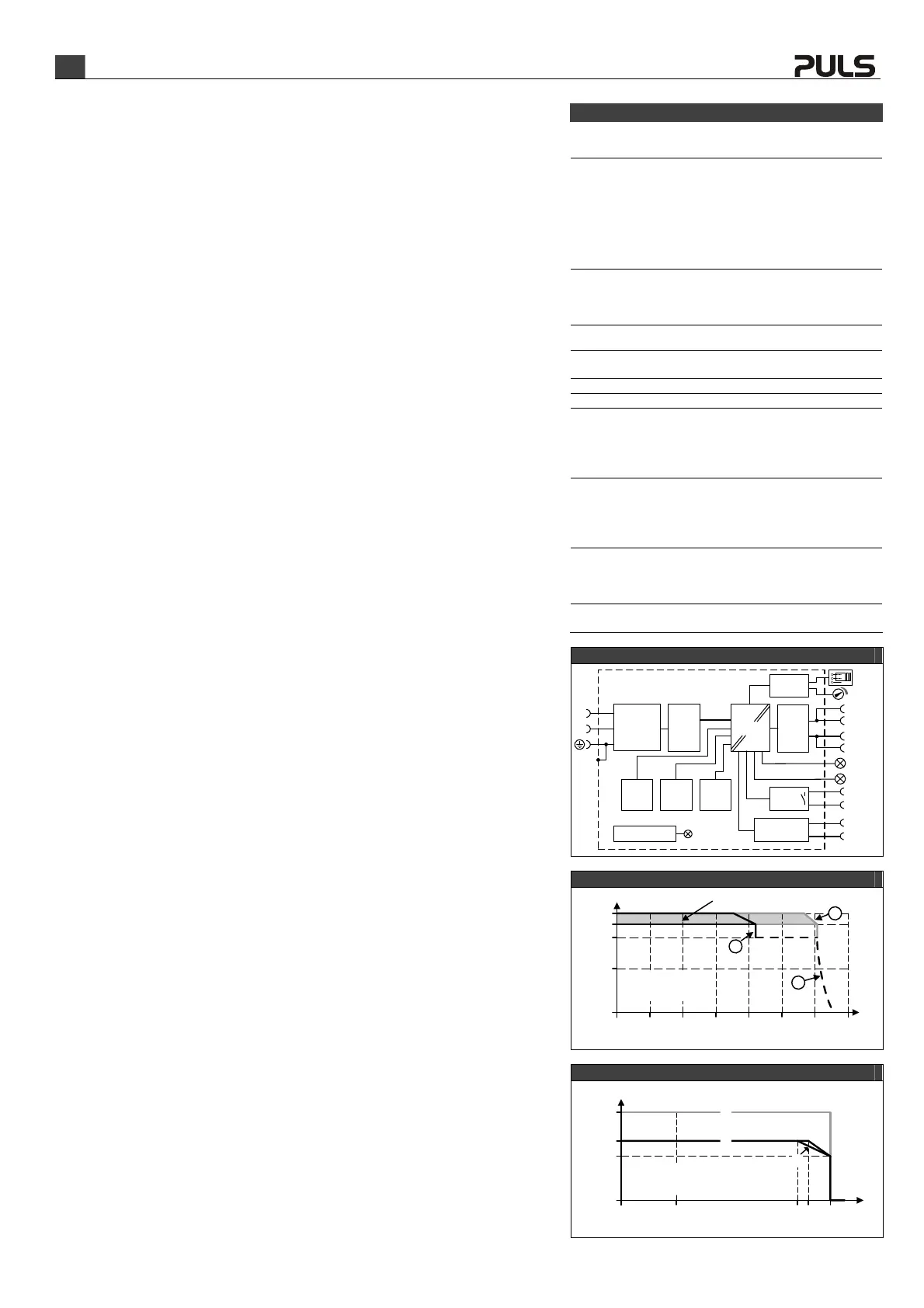
Temperature Range
Allowed output current at 24V
Ambient temperature
0A
-25
60A
0 +70°C
30A
A
40A
60
A: continuous (90-264Vac)
B: continuous (85-90Vac)
C: up to 4s
55
C
B
 Loading...