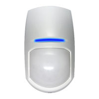
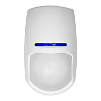
KX15DT
®
15m Dual Technology
Digital Detector
1: Disassembling the KX
4: Bracket Connections 6: Sensitivity Settings
7: AND/OR Mode
8: Microwave Potentiometer5: Installation Hints 9: EOL Resistor Headers
a) Auto Sensitivity (Default)
b) Wall Bracket
Fitting
a) Ceiling
Bracket
Fitting
b) High Sensitivity
ALARM CONTROL PANEL
+
-
ZONE1
COM
TAMPER
TAMPER
ALARM CONTROL PANEL
+
-
ZONE1
COM
TAMPER
TAMPER
ALARM CONTROL PANEL
+
-
ZONE1
COM
TAMPER
TAMPER
KX
KXKX
1K
1K
ALARM
TAMPER
TAMPERALM ALM
+ -
5K6
5K6
6K8
4K7
4K7
2K2
1K
1K
ALARM
TAMPER
TAMPERALM ALM
+ -
5K6
5K6
6K8
4K7
4K7
2K2
1K
1K
ALARM
TAMPER
TAMPERALM ALM
ALARM CONTROL PANEL
+
-
ZONE1
COM
TAMPER
TAMPER
+ -
Link
+ -
KX
+ -
5K6
5K6
6K8
4K7
4K7
2K2
1K
1K
ALARM
TAMPER
TAMPERALM ALM
KX
+ -
5K6
5K6
6K8
4K7
4K7
2K2
1K
1K
ALARM
TAMPER
TAMPERALM ALM
ALARM CONTROL PANEL
+
-
ZONE1
COM
TAMPER
TAMPER
+ -
Link
+ -
KX
+ -
5K6
5K6
6K8
4K7
4K7
2K2
1K
1K
ALARM
TAMPER
TAMPERALM ALM
KX
+ -
5K6
5K6
6K8
4K7
4K7
2K2
1K
1K
ALARM
TAMPER
TAMPERALM ALM
2K2
Hard Wired
Resistor
ALARM CONTROL PANEL
+
-
ZONE1
COM
TAMPER
TAMPER
ALARM CONTROL PANEL
+
-
ZONE1
COM
TAMPER
TAMPER
ALARM CONTROL PANEL
+
-
ZONE1
COM
TAMPER
TAMPER
KX
KX
+ -
5K6
5K6
6K8
4K7
4K7
2K2
1K
1K
ALARM
TAMPER
TAMPERALM ALM
+ -
5K6
5K6
6K8
4K7
4K7
2K2
1K
1K
ALARM
TAMPER
TAMPERALM ALM
+ -
5K6
5K6
6K8
4K7
4K7
2K2
1K
1K
ALARM
TAMPER
TAMPERALM ALM
ALARM CONTROL PANEL
+
-
ZONE1
COM
TAMPER
TAMPER
+ -
Link
+ -
KX
+ -
5K6
5K6
6K8
4K7
4K7
2K2
1K
1K
ALARM
TAMPER
TAMPERALM ALM
KX
+ -
5K6
5K6
6K8
4K7
4K7
2K2
1K
1K
ALARM
TAMPER
TAMPERALM ALM
ALARM CONTROL PANEL
+
-
ZONE1
COM
TAMPER
TAMPER
+ -
Link
+ -
KX
+ -
5K6
5K6
6K8
4K7
4K7
2K2
1K
1K
ALARM
TAMPER
TAMPERALM ALM
KX
+ -
5K6
5K6
6K8
4K7
4K7
2K2
1K
1K
ALARM
TAMPER
TAMPERALM ALM
2K2
Hard Wired
Resistor
b) Single End of Line Wiring
ALARM CONTROL PANEL
+
-
ZONE1
COM
TAMPER
TAMPER
ALARM CONTROL PANEL
+
-
ZONE1
COM
TAMPER
TAMPER
ALARM CONTROL PANEL
+
-
ZONE1
COM
TAMPER
TAMPER
KX
KXKX
+ -
5K6
5K6
6K8
4K7
4K7
2K2
1K
1K
ALARM
TAMPER
TAMPERALM ALM
+ -
5K6
5K6
6K8
4K7
4K7
2K2
1K
1K
ALARM
TAMPER
TAMPERALM ALM
+ -
5K6
5K6
6K8
4K7
4K7
2K2
1K
1K
ALARM
TAMPER
TAMPERALM ALM
ALARM CONTROL PANEL
+
-
ZONE1
COM
TAMPER
TAMPER
+ -
Link
+ -
KX
+ -
5K6
5K6
6K8
4K7
4K7
2K2
1K
1K
ALARM
TAMPER
TAMPERALM ALM
KX
+ -
5K6
5K6
6K8
4K7
4K7
2K2
1K
1K
ALARM
TAMPER
TAMPERALM ALM
ALARM CONTROL PANEL
+
-
ZONE1
COM
TAMPER
TAMPER
+ -
Link
+ -
KX
+ -
1K
1K
ALARM
TAMPER
TAMPERALM ALM
KX
+ -
1K
1K
ALARM
TAMPER
TAMPERALM ALM
ALARM CONTROL PANEL
+
-
ZONE1
COM
TAMPER
TAMPER
ALARM CONTROL PANEL
+
-
ZONE1
COM
TAMPER
TAMPER
ALARM CONTROL PANEL
+
-
ZONE1
COM
TAMPER
TAMPER
KX
KXKX
+ -
5K6
5K6
6K8
4K7
4K7
2K2
1K
1K
ALARM
TAMPER
TAMPERALM ALM
+ -
5K6
5K6
6K8
4K7
4K7
2K2
1K
1K
ALARM
TAMPER
TAMPERALM ALM
+ -
5K6
5K6
6K8
4K7
4K7
2K2
1K
1K
ALARM
TAMPER
TAMPERALM ALM
ALARM CONTROL PANEL
+
-
ZONE1
COM
TAMPER
TAMPER
+ -
Link
+ -
KX
+ -
5K6
TAMPERALM ALM
KX
+ -
5K6
5K6
6K8
4K7
4K7
2K2
1K
1K
ALARM
TAMPER
TAMPERALM ALM
ALARM CONTROL PANEL
+
-
ZONE1
COM
TAMPER
TAMPER
+ -
Link
+ -
KX
+ -
5K6
5K6
6K8
4K7
4K7
2K2
1K
1K
ALARM
TAMPER
TAMPERALM ALM
KX
+ -
5K6
5K6
6K8
4K7
4K7
2K2
1K
1K
ALARM
TAMPER
TAMPERALM ALM
2K2
Hard Wired
Resistor
ALARM CONTROL PANEL
+
-
ZONE1
COM
TAMPER
TAMPER
ALARM CONTROL PANEL
+
-
ZONE1
COM
TAMPER
TAMPER
ALARM CONTROL PANEL
+
-
ZONE1
COM
TAMPER
TAMPER
KX
KXKX
+ -
5K6
5K6
6K8
4K7
4K7
2K2
1K
1K
ALARM
TAMPER
TAMPERALM ALM
+ -
5K6
5K6
6K8
4K7
4K7
2K2
1K
1K
ALARM
TAMPER
TAMPERALM ALM
+ -
5K6
5K6
6K8
4K7
4K7
2K2
1K
1K
ALARM
TAMPER
TAMPERALM ALM
ALARM CONTROL PANEL
+
-
ZONE1
COM
TAMPER
TAMPER
+ -
Link
+ -
KX
+ -
5K6
5K6
6K8
4K7
4K7
2K2
1K
1K
ALARM
TAMPER
TAMPERALM ALM
KX
+ -
5K6
5K6
6K8
4K7
4K7
2K2
1K
1K
ALARM
TAMPER
TAMPERALM ALM
ALARM CONTROL PANEL
+
-
ZONE1
COM
TAMPER
TAMPER
+ -
Link
+ -
KX
+ -
5K6
5K6
6K8
4K7
4K7
2K2
1K
1K
ALARM
TAMPER
TAMPERALM ALM
KX
+ -
5K6
5K6
6K8
4K7
4K7
2K2
1K
1K
ALARM
TAMPER
TAMPERALM ALM
ALARM CONTROL PANEL
+
-
ZONE1
COM
TAMPER
TAMPER
ALARM CONTROL PANEL
+
-
ZONE1
COM
TAMPER
TAMPER
ALARM CONTROL PANEL
+
-
ZONE1
COM
TAMPER
TAMPER
KX
KXKX
+ -
5K6
5K6
6K8
4K7
4K7
2K2
1K
1K
ALARM
TAMPER
TAMPERALM ALM
+ -
5K6
5K6
6K8
4K7
4K7
2K2
1K
1K
ALARM
TAMPER
TAMPERALM ALM
+ -
5K6
5K6
6K8
4K7
4K7
2K2
1K
1K
ALARM
TAMPER
TAMPERALM ALM
ALARM CONTROL PANEL
+
-
ZONE1
COM
TAMPER
TAMPER
+ -
Link
+ -
KX
+ -
5K6
5K6
6K8
4K7
4K7
2K2
1K
1K
ALARM
TAMPER
TAMPERALM ALM
KX
+ -
5K6
5K6
6K8
4K7
4K7
2K2
1K
1K
ALARM
TAMPER
TAMPERALM ALM
ALARM CONTROL PANEL
+
-
ZONE1
COM
TAMPER
TAMPER
+ -
Link
+ -
KX
+ -
5K6
5K6
6K8
4K7
4K7
2K2
1K
1K
ALARM
TAMPER
TAMPERALM ALM
KX
+ -
5K6
5K6
6K8
4K7
4K7
2K2
1K
1K
ALARM
TAMPER
TAMPERALM ALM
2K2
Hard Wired
Resistor
c) Double End of Line Wiring d) Two Double End of Line Detectors to One Input e) Zone Doubling Example (For Matrix 424, 832, 832+)
14: Technical Specication 15: Compliance and Warranty 16: Contact Information
2: The Printed Circuit Board
3: Cable Entry + Mounting
10: Choose the Connection Type: 11: Powering Up
12: The 15m Volumetric Lens 13: Dimensions and Weight
b) Lens Illuminator
a) Printed Circuit Board
d) Lens Holder
c) Lens
f) Back
Tamper
e) PCB
Screw
f) Nut
g) Casing Screw
h) Microwave
Potentiometer
f) Tamper and Alarm
Resistor Headers
a) Terminals
a) Mounting Screw
Knockouts
b) Cable Entry
Knockout
c) Case Lid Screw
Fitting
b) Mains Frequency
c) Sensitivity Auto/High
See Section 6
d) AND/OR
e) ALARM LED
See section 7
50Hz
(Default)
LED Disable
60Hz
LED Enable
(Default)
g) Pyro Sensor
DO NOT TOUCH
The KX15DT has 2 set of header pins at the top of
the printed circuit board. These headers are used
to select the End of Line resistance for EOL wiring
applications.
If EOL wiring is not used, leave the headers OFF.
Note: turning pot fully anti-clockwise turns o
microwave
Conventional Dual Tech (Both technologies need to
be triggered simultaneously to generate an alarm)
AND
OR
If either single technology detects prolonged
intruder activity an alarm will be generated
The connection shows the
example values 4k7 for alarm,
4k7 for tamper (EOL). And 2K2
for the zone doubling EOL.
The connection shows
the example values
4k7 for alarm, 4k7 for
tamper (EOL).
The
connection
shows the
example value
4k7 for tamper
(EOL).
The
connection
shows the
example
values of 4k7
for Alarm and
4K7 for tamper
(EOL).
Avoiding False Alarms
Model: KX15DT
Colour: White
LED Colours: Orange (Microwave), Blue (Alarm),
Green (PIR)
Casing: 3mm ABS, 0.4mm HDPE in Lens Area
Detection Method: Low noise dual element
pyroelectric sensor and Microwave Doppler Sensor
PIR Sensitivity: Auto or High
Temperature Comp: Digital
Detection Range: 15m (13m according to EN
50131-2-4 and INCERT)
Detection Speed: 0.3 - 3.0m/s
Operating Voltage: 9-16V DC 13.8V DC typical
117 x 69 x 50mm
125g (4.4 oz)
without bracket
Current Consumption: 24mA @ 12V (Min), 30mA @
12V (Max)
Relay Output: 50mA 60 VDC, 42 VAC (RMS)
Contact Resistance: <10ohms
Mounting Height: 1.8m - 2.4m
Tamper Switch: 12V 50mA
Storage Temp: -40°C to 80°C
Certied operating temperature: -10°C to 40°C
Nominal working temperature: -30°C to 70°C
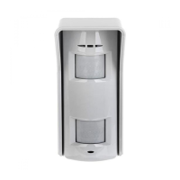
Accessories: Wall and Ceiling brackets
Emissions: EN55022 Class B
Immunity: EN50130-4
The Installation of The KX15DD
CABLE ENTRY
KNOCKOUT
CASE LID
SCREW FITTING
The KX15DD Casing
Wall Mounting
NOTE: When
mounting the
detector, ensure
that it is not
tilting backwards.
KX15DDKX15DD
Control PanelControl Panel Control Panel
KX15DD
Control Panel
KX15DD
Control Panel
KX15DD
Wall Bracket Fitting
Ceiling Bracket Fitting
Auto Sensitivity
Normally Closed Wiring
Zone Doubling Example (Matrix 424,832 or 832+)
Two DEOL Detectors To One Input
Single End of Line Wiring (SEOL)
Double End of Line Wiring (DEOL)
Remote LED Enable
High Sensitivity Low Sensitivity
OFF ON (Default)
SENSITIVITY SETTINGS:
Auto, High or Low.
See the diagams below
5K6
4K7
2K2
1K
+ – ALARM TAMPER LED
Alarm LED
Pyro Sensor
EOL Resistance
Headers
EOL Resistor Headers
The KX15DD Printed Circuit Board
The Wiring Connections For The KX15DD (Examples using 4k7 for alarm, 4k7 for tamper)
The KX15DD has two sets of header pins on the PCB, one on
either side of the connector blocks. These headers are used to
select the End Of Line resistance for EOL wiring applications.
If EOL wiring is not used, leave the headers OFF.
The set to the left of the + terminal selects the value of the
resistance across the ALARM relay. The set to the right of the
TAMPER terminals selects the value of the End Of Line resistor.
If the resistance value you require
is not selectable, leave the
headers off and wire a resistor
of the required value between the
appropriate terminals as shown.
The KX15DD has a terminal marked ‘LED’ which can be used
to enable the LED in walk test only on a alarm control panel.
This is used when the LED is disabled via the LED ON/OFF link.
To enable this feature, the LED terminal needs to be connected
to an Output at the alarm control panel. When the system is
is in walk test mode the Output should be at 0V.
The Output would be usually programmed as “Remote LED
enable”.
The KX15DD sensitivity is selected by
the two headers located at the bottom
of the PCB
The sensitivity can be either AUTO,
HIGH or LOW.
To select either of these sensivities
please see the diagrams below.
This symbol illustrates
where the resistors are
connected internally
6K8
5K6
4K7
2k2
1K
LOW AUTO AUTO HI
6K8
5K6
4K7
2k2
1K
5K6
4K7
2K2
1K
+ – ALARM TAMPER LED
LOW AUTO AUTO HI
LOW AUTO AUTO HI
+ – ALARM TAMPER LED
Control Panel
Output
(0v in Walk Test)
6K8
5K6
4K7
2k2
1K
5K6
4K7
2K2
1K
+ – ALARM TAMPER LED
LOW AUTO AUTO HI
LOW AUTO AUTO HI
T T+AUX- Z1
COM
5K6
4K7
2K2
1K
5K6
4K7
2K2
1K
+ – ALARM TAMPER LED
6K8
5K6
4K7
2K2
1K
6K8
5K6
4K7
2K2
1K
T T+AUX- Z1
COM
5K6
4K7
2K2
1K
5K6
4K7
2K2
1K
+ – ALARM TAMPER LED
6K8
5K6
4K7
2K2
1K
6K8
5K6
4K7
2K2
1K
T T+AUX- Z1
COM
5K6
4K7
2K2
1K
5K6
4K7
2K2
1K
+ – ALARM TAMPER LED
6K8
5K6
4K7
2K2
1K
6K8
5K6
4K7
2K2
1K
+AUX-
T T+AUX- Z1
COM
5K6
4K7
2K2
1K
5K6
4K7
2K2
1K
+ – ALARM TAMPER LED
6K8
5K6
4K7
2K2
1K
6K8
5K6
4K7
2K2
1K
6K8
5K6
4K7
2K2
1K
6K8
5K6
4K7
2K2
1K
+AUX-
Link
5K6
4K7
2K2
1K
5K6
4K7
2K2
1K
+ – ALARM TAMPER LED
+AUX-
+AUX-
T T+AUX- Z1
COM
Link
5K6
4K7
2K2
1K
5K6
4K7
2K2
1K
5K6
4K7
2K2
1K
5K6
4K7
2K2
1K
+ – ALARM TAMPER LED
+ – ALARM TAMPER LED
6K8
5K6
4K7
2K2
1K
6K8
5K6
4K7
2K2
1K
6K8
5K6
4K7
2K2
1K
6K8
5K6
4K7
2K2
1K
6K8
5K6
4K7
2k2
1K
5K6
4K7
2K2
1K
+ – ALARM TAMPER LED
LOW AUTO AUTO HI
LOW AUTO AUTO HI
This is the default
setting
RINS1038-3
®
®
®
®
®
®
C
D
E
C1 C2 C3
C4
E1 E2 E3
E5E4
C5
®
®
®
®
®
When the detector is rst powered up, it will run
through a self-test routine, indicated by the ashing
LEDs. Once this has distinguished the detector is
ready to use.
1. Avoid placing the detector in direct sunlight.
2. Do not let pets and other animals wander freely
whilst the alarm system is armed.
3. Do not mount the detector near heaters or
radiators.
4. Do not mount the detector near open windows or
Do not partially or completely obscure the detector’s
eld of view with large objects such as furniture.
The Installation of The KX15DD
CABLE ENTRY
KNOCKOUT
CASE LID
SCREW FITTING
The KX15DD Casing
Wall Mounting
NOTE: When
mounting the
detector, ensure
that it is not
tilting backwards.
KX15DDKX15DD
Control PanelControl Panel Control Panel
KX15DD
Control Panel
KX15DD
Control Panel
KX15DD
Wall Bracket Fitting
Ceiling Bracket Fitting
Auto Sensitivity
Normally Closed Wiring
Zone Doubling Example (Matrix 424,832 or 832+)
Two DEOL Detectors To One Input
Single End of Line Wiring (SEOL)
Double End of Line Wiring (DEOL)
Remote LED Enable
High Sensitivity Low Sensitivity
OFF ON (Default)
SENSITIVITY SETTINGS:
Auto, High or Low.
See the diagams below
5K6
4K7
2K2
1K
+ – ALARM TAMPER LED
Alarm LED
Pyro Sensor
EOL Resistance
Headers
EOL Resistor Headers
The KX15DD Printed Circuit Board
The Wiring Connections For The KX15DD (Examples using 4k7 for alarm, 4k7 for tamper)
The KX15DD has two sets of header pins on the PCB, one on
either side of the connector blocks. These headers are used to
select the End Of Line resistance for EOL wiring applications.
If EOL wiring is not used, leave the headers OFF.
The set to the left of the + terminal selects the value of the
resistance across the ALARM relay. The set to the right of the
TAMPER terminals selects the value of the End Of Line resistor.
If the resistance value you require
is not selectable, leave the
headers off and wire a resistor
of the required value between the
appropriate terminals as shown.
The KX15DD has a terminal marked ‘LED’ which can be used
to enable the LED in walk test only on a alarm control panel.
This is used when the LED is disabled via the LED ON/OFF link.
To enable this feature, the LED terminal needs to be connected
to an Output at the alarm control panel. When the system is
is in walk test mode the Output should be at 0V.
The Output would be usually programmed as “Remote LED
enable”.
The KX15DD sensitivity is selected by
the two headers located at the bottom
of the PCB
The sensitivity can be either AUTO,
HIGH or LOW.
To select either of these sensivities
please see the diagrams below.
This symbol illustrates
where the resistors are
connected internally
6K8
5K6
4K7
2k2
1K
LOW AUTO AUTO HI
6K8
5K6
4K7
2k2
1K
5K6
4K7
2K2
1K
+ – ALARM TAMPER LED
LOW AUTO AUTO HI
LOW AUTO AUTO HI
+ – ALARM TAMPER LED
Control Panel
Output
(0v in Walk Test)
6K8
5K6
4K7
2k2
1K
5K6
4K7
2K2
1K
+ – ALARM TAMPER LED
LOW AUTO AUTO HI
LOW AUTO AUTO HI
T T+AUX- Z1
COM
5K6
4K7
2K2
1K
5K6
4K7
2K2
1K
+ – ALARM TAMPER LED
6K8
5K6
4K7
2K2
1K
6K8
5K6
4K7
2K2
1K
T T+AUX- Z1
COM
5K6
4K7
2K2
1K
5K6
4K7
2K2
1K
+ – ALARM TAMPER LED
6K8
5K6
4K7
2K2
1K
6K8
5K6
4K7
2K2
1K
T T+AUX- Z1
COM
5K6
4K7
2K2
1K
5K6
4K7
2K2
1K
+ – ALARM TAMPER LED
6K8
5K6
4K7
2K2
1K
6K8
5K6
4K7
2K2
1K
+AUX-
T T+AUX- Z1
COM
5K6
4K7
2K2
1K
5K6
4K7
2K2
1K
+ – ALARM TAMPER LED
6K8
5K6
4K7
2K2
1K
6K8
5K6
4K7
2K2
1K
6K8
5K6
4K7
2K2
1K
6K8
5K6
4K7
2K2
1K
+AUX-
Link
5K6
4K7
2K2
1K
5K6
4K7
2K2
1K
+ – ALARM TAMPER LED
+AUX-
+AUX-
T T+AUX- Z1
COM
Link
5K6
4K7
2K2
1K
5K6
4K7
2K2
1K
5K6
4K7
2K2
1K
5K6
4K7
2K2
1K
+ – ALARM TAMPER LED
+ – ALARM TAMPER LED
6K8
5K6
4K7
2K2
1K
6K8
5K6
4K7
2K2
1K
6K8
5K6
4K7
2K2
1K
6K8
5K6
4K7
2K2
1K
6K8
5K6
4K7
2k2
1K
5K6
4K7
2K2
1K
+ – ALARM TAMPER LED
LOW AUTO AUTO HI
LOW AUTO AUTO HI
This is the default
setting
RINS1038-3
®
®
®
®
®
®
C
D
E
C1 C2 C3
C4
E1 E2 E3
E5E4
C5
®
®
®
®
®
Minimum
Range (0m)
Maximum
Range (15m)
85°
60 zones
7 planes
RLNS074
85°
60 zones
7 planes
RLNS074
* In an EN50131-1 (and INCERT) system the
maximum detection is 13m.
When the detector is rst powered up, it will run
through a self-test routine, indicated by the ashing
LEDs. Once this has distinguished the detector is
ready to use.
NOT READY
READY
Secure Holdings, Pyronix Ltd,
Braithwell Way, Hellaby,
Rotherham, South Yorkshire
S66 8QY
For electrical products sold within
the European Community. At the
end of the electrical products useful
life, it should not be disposed of with
household waste. Please recycle
where facilities exist. Check with your
Local Authority or retailer for recycling
advice in your country.
Customer Support:
+44(0)845 6434 999 (local rate)
or +44(0)1709 535225
Hours: Mon to Fri, 8:00am till 6:30pm
Email: customer.support@pyronix.com
Website: www.pyronix.com
Hereby, Pyronix Ltd, declares that this product is in
compliance with the essential requirements
and other relevant provisions of Directive 1999/5/EC, and
EN50131-2-4:2008 at Security grade (SG) 2,
Environmental class (EC) II. This product is approved for
use in the Residential, Commercial and Light Industrial
Environment. It is suitable to be installed with
UK systems to PD6662:2010,
and EXPORT systems installed to EN501311:2006+A1:2009
The declaration of conformity may be consulted at
www.pyronix.com/product-compliance
WARRANTY: This product is sold subject to our standard
warranty conditions and is warranted against defects in
workmanship for a period of ve years. In the interest
of continuing improvements of quality, customer care
and design, Pyronix ltd reserves the right to amend
specications without giving prior notice.
Visit www.pyronix.com/warranty for more information.
Frequencies
Countries
AT, BE, CH, CY, CZ,
DK, FI, FR, GR, HU, IE,
IS, IT, LT, MT, NL, PL,
SI,T R
BE, CH, CY, DK, HU,
IE, IS, IT, MT, NL, NO,
SE, SI
GB
9.9Ghz
10.525Ghz
10.587Ghz
®
This product operates in a European non-harmonised
frequency band
!
TS50131-2-4
EN50131-1
PD6662:2004
Security Grade 3
Environmental Class 2
TS50131-2-4
EN50131-1
PD6662:2004
Security Grade 2
Environmental Class 2
TS50131-2-2
EN50131-1
PD6662:2004
Security Grade 2
Environmental Class 2
3
RINS549-13
EN50131-2-4:2008
EN50131-1
PD6662:2010
Security Grade (SG) 2
Environmental Class (EC) II