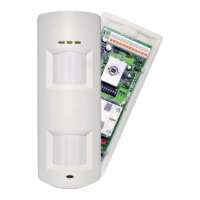
Physical Layout
+
-
TAMPER
ALARM 1 ALARM 2
RI1/SPARE
anti-mask/FAULT EOL
anti-mask/FAULT
RI 1
LED
EOLEOLEOLEOLEOL
anti-mask/FAULT
ALARM 1
ALARM
2
TAMPER
TAMPER
1K
2K2
4K7
5K6
6K8
8K2
12K
15K
3K
1K
1K
1K
1K
0
2K2
2K2
2K2
2K2
4K7
4K7
4K7
4K7
5K6
5K6
5K6
5K6
6K8
6K8
MW Range Adjust
AM Adjust
1
K
S
O
N
2
3
4
5
6
7
8
Pyro Sensor
Pyro Sensor
EOL Resistance
Headers
(TAMPER,
ALARM 1,
anti-mask/FAULT)
Dual Tech
EOL Resistance
Headers
Single PIR
(TAMPER,
ALARM 2)
DIP
Switches
PIR
Range:
5, 10 or 15m
(15m top)
Microwave
Module
LEDs
Orange (Microwave)
Blue (Alarm)
Green (PIR)
Left =
Center =
Right =
LED
Red (Alarm)
Front
Tamper
Anti-mask EOL
Header
Disabled
Enabled
RI1/Spare
Microwave Adjust
Decrease
Sensitivity
()1m
Increase
Sensitivity
()15m
Increase
Sensitivity
()1m
(Must be at 0.1m - 1m
to be EN compliant)
FULLY ANTI-CLOCKWISE
TURNS THE anti-mask OFF
Anti-mask Adjust
The Tampers
Dip Switches
Front Tamper
Back Tamper
Case Lid
Screw
3K
3K
Grade 3 Configuration (DEOL)
TriCover® mode configured to a single input with anti-mask
configured to a second input
Case Lid Screw Fitting
Wall Mounting
Casing Knockouts
NOTE: When mounting the TMD 15,
ensure that it is mounted vertically
Rear Tamper
Break Out
(See “The
Tamper”
section)
Make sure a
10mm gap exists
between the ceiling
and the top of the
TMD before fixing.
PIR Range
Wall Fixing
Knockouts
NOTE: IF THE RESISTOR VALUES THAT YOU REQUIRE ARENT SHOWN, PLEASE CONTACT CUSTOMER SUPPORT.
Grade 2 Configuration
Dual Tech and Single PIR Technologies
Configured To Separate Inputs (SEOL)
Dual tech to input 1
Single PIR to input 2
Single PIR
Single PIR
anti-mask/FAULT
anti-mask/FAULT
ALARM 1
ALARM 1
TAMPER
TAMPER
1K
1K
2K2
2K2
4K7
4K7
5K6
5K6
6K8
6K8
8K2
8K2
12K
12K
15K
15K
1K
1K
1K
1K
2K2
2K2
2K2
2K2
4K7
4K7
4K7
4K7
5K6
5K6
5K6
5K6
6K8
6K8
Dual Tech
Dual Tech
ALARM 2
ALARM 2
TAMPER
TAMPER
1K
1K
1K
1K
0
0
2K2
2K2
2K2
2K2
4K7
4K7
4K7
4K7
5K6
5K6
5K6
5K6
6K8
6K8
3K
Single PIR
anti-mask/FAULT
ALARM 1
TAMPER
1K
2K2
4K7
5K6
6K8
8K2
12K
15K
1K
1K
2K2
2K2
4K7
4K7
5K6
5K6
6K8
Dual Tech
ALARM 2
TAMPER
1K
1K
0
2K2
2K2
4K7
4K7
5K6
5K6
6K8
Hard Wired
Resistor
(This example
would be 4k7)
Hard Wired
Resistor
(This example
would be 4k7)
ANTI-MASK
FAULT EOL
LINK MUST
BE OFF
ANTI-MASK
FAULT EOL
LINK MUST
BE OFF
ANTI-MASK
FAULT EOL
LINK MUST
BE OFF
The Wiring Connections For The TMD15 (Examples)
®
On Off
1
KS
ON
2
3
4
5
6
7
8
Enable LEDs
2 Movement Detector
Open Mask & Alarm Relays
Dual Tech Auto Sensitivity
Set Mode
Blocking Off
24 Hour
50Hz
Disable LEDs
TriCover Detector
Open Mask Relay
Dual Tech High Sensitivity
RI 1 Mode
Blocking On
anti-mask only in unset
60Hz
®
Grade 2 Configuration
TriCover® Mode SEOL Wired to a single input with anti-mask
configured to a second input
The back tamper operates by the use of the “rear
tamper break out” section of the TMD 15. If the
detector is forcibly removed the “rear tamper
break out” stays attached to the wall, thus opening
the back tamper.
®
®
The Installation Of The TMD15
®
10mm
+
-
TAMPER
ALARM 1 ALARM 2
RI 1 / SPARE
anti-mask/FAULTEOL
anti-mask/FAULT
RI 1
LED
EOLEOLEOLEOLEOL
anti-m
ask/F
AU
L
T
ALA
RM
1
ALAR
M
2
TAM
PER
TAM
PER
1K
2K2
4K7
5K6
6K8
8K2
12K
15K
3K
1K
1K
1K
1K
0
2K2
2K2
2K2
2K2
4K7
4K7
4K7
4K7
5K6
5K6
5K6
5K6
6K8
6K8
MW Range Adjust
AM Adjust
1
KS
ON
2
3
4
5
6
7
8
The ‘notches’ as shown above, alter the range
of the PIR from 5m to 15m.
Top = 15m
Middle = 10m
Bottom = 5m
Decrease
Sensitivity
()0m
NOTE: DIP SWITCH 7 MUST BE OFF
NOTE: DIP SWITCH 7 MUST BE OFF
Z2
+
-
TAMPER
ALARM 1 ALARM 2
RI1/SPARE
MASK/FAULT EOL
anti-mask/FAULT
RI 1
LED
EOLEOLEOLEOLEOL
+AUX-
Z1
COM
Z2
Z2
+
-
TAMPER
ALARM 1 ALARM 2
RI1/SPARE
MASK/FAULT EOL
anti-mask/FAULT
RI 1
LED
EOLEOLEOLEOLEOL
+AUX-
+AUX-
Z1
Z1
COM
COM
+
-
TAMPER
ALARM 1 ALARM 2
RI1/SPARE
MASK/FAULT EOL
anti-mask/FAULT
RI 1
LED
EOLEOLEOLEOLEOL

 Loading...