oponal QK-BRALUX
INSTALLING RADIO MODULE
Important noce: radio module is by factory installed on the control board plasc box. The radio
signal range is good enough in most cases. Shall you wish to increase the radio range even more,
install the radio module as one the following examples.
Quiko Italy declares under their own responsibility that the product complies with the main safety requirements issued
by the following direcves: 1) Radio Sets 1999/05/EC – 2) Low voltage 2006/95/EC – 3) Electromagnec compability
2004/108/EC and any revisions thereof, and complies with the provisions that implement said direcves in the naonal
legislaon of the Country where the products are to be used.
MADE IN ITALY
quikoitaly.com
CHECKING IF THE MOTORS TURN IN THE RIGHT DIRECTION
1. Remove electricity.
2. Unlock both motors and manually put the leafs in the middle.
3. Give electricity.
4. Give a first start impulse to the system with remote control or push - buon.
5. Make sure that both motors open.
6. If one or both motors closes instead, swap the phases cables of the motor/s that was closing.
7. Once you have swapped motor/s phases cables, repeat the procedure above and make sure that
now both motors open at first start signal aer giving electricity.
8. The system is now ready for setup.
Once all the connecons have been done and the system is ready to start, before seng the system
it is important to check that the motors turn in the right direcon. To do that:
MB
17
1816
MOTOR A
MA
14
1513
First motor to open, last motor to close.
13 open
14 common
15 close
16 open
17 common
18 close
MOTOR B
13
15
16
18
QK-CE220BATRL4
QUICK GUIDE
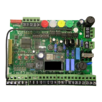
CONTROL BOARD FOR 230V SWING GATES
INPUTS / OUTPUTS CONNECTION
START N.O.
E1
Go
=
2 3
4
1
8 9 10
11
12
7
STOP N.C.
E2
St
=
2 3
4
1
8 9 10
11
12
7
E7
PE
=
PEDESTRIAN N.O.
8 9 10
11
12
7
230 VAC
X
2019
N
L
neutral
phase
24 VDC OUTPUT FLASHING LAMP
24 VAC 20W
8 9 10
7
11
12
-24V+24V COM
400mA
8 9 10
7
11
12
MOTOR A
MA
14
1513
MOTOR B
MB
17
1816
13 open / 14 common / 15 close 16 open / 17 common / 18 close
First motor to open, last motor to close.
QK-CE220BATRL4
PHOTOCELLS RECEIVER
PHOTOCELLS TRANSMITTER WITHOUT PHOTO TEST FUNCTION
INTERNAL / OPENING PHOTOCELLS EXTERNAL / CLOSING PHOTOCELLS
N.C.
2 3
4
1
8 9 10
11
12
7
-24V
+24V COM
2 3
4
1
8 9 10
11
12
7
-24V
+24V COM
2 3
4
1
8 9 10
11
12
7
-24V
+24V COM
2 3
4
1
8 9 10
11
12
7
-24V
+24V COMN.C.
2 3
4
1
8 9 10
11
12
7
-24V
+24V COM
2 3
4
1
8 9 10
11
12
7
-24V
+24V COM
DISABLED BY SOFTWARE
E4 no E3 no
==
Make sure that the contact is not bridged.
PHOTOCELLS TRANSMITTER WITH PHOTO TEST FUNCTION
t1 SI
=
t1 SI
=
PHOTOCELLS CONNECTION
QUICK GUIDE
CONTROL BOARD FOR 230V SWING GATES
STOP N.C.
PEDESTRIAN N.O.
+24V DC / COMMON
PHOTOCELLS TEST
-24V DC
OPEN
MOTOR A
MOTOR B
CLOSE
OPEN
CLOSE
230 VAC
N
POWER
14
13
X
2019
15
16
17
18
2 3
1
8 9 10
11
124
7
+24V
230V
N
A
B
C
D
+
-
RED
BLACK
WHITE
antenna
RX MODULE
COMMON
COMMON
SIGNAL
SCREEN
RX MODULE: put inside flashing lamp
or antenna housing to increase range
of radio signal.
EXT PHOTOCELL
N.C.
INT PHOTOCELL
N.C.
START
N.O.
FLASHING LAMP 24V AC
FLASHING LAMP 24V AC
OPTIONAL MODULE
QK-ELOCKM
12 V ELECTRIC LOCK
QK-ELOCKM
LO SI
=
In the case you want to connect an
external RG59 cabled antenna please
connect signal and screen as per the
image above.
INSIDE THE ANTENNA HOUSING INSIDE THE FLASHING LAMP
oponal
QK-AN433_V4
ANTENNA HOUSING WITH
FLASHING LAMP
BLACK
BLACK
RED
RED
MADE IN ITALY
®
MADE IN ITALY
®
MADE IN ITALY
®
®
V21
Hb2117
V21
Hb2117