2 3 4 5 6
Mount the Indoor Amplier
You can mount the indoor ampl ier to a wall
with the supplied screws.
Installation Tips
• Performance can var y greatly by
location. After you install the ampli er,
set FM TRAP on t he outdoor amplier
to ON, and adjust GAIN on th e indoor amplier. You may want
to try severa l GAIN settings to nd the best reception.
• Be sure to set FM TRA P when you connect the outdoor
ampli er to the antenna. Set to ON to prevent FM signal
interference. Set to OFF if connecting to an FM radio.
• Remember to scan for channels (refer to your television user’s
guide) after adjusting GAIN.
•
Antenna signals are direc tional; installing an antenna rotator
can help you position the antenna to receive t he optimal signal.
• Coaxial cables are available at your local Rad ioShack store or
online at w ww.radioshack .com.
We h ope you e njoy your Hig h-Gai n Sig nal Ampl ifi er f rom
Rad ioSh ack. Plea se rea d th is us er’s guid e bef ore i nsta llin g, s etti ng
up, and usin g you r new sig nal a mpli fie r.
1500526
User’s Guide
Antenna-Mounted
High-Gain Signal Amplifier
Package Contents
• Outdoor Amplier
• Indoor Amplier
• AC Adapter
• 6-Foot Coaxial Cable with Weatherboots
• 6-Foot Coaxial Cable with out Weatherboots
• U-Bolt wit h Nuts (4) and Washers (4)
• 75-ohm Terminator
• Spare Weatherboot
• Mounting Screw (2)
• User’s Guide
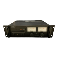
Feature
• Amplies HDTV, VHF, UHF, and FM signals
• Gain control
• Filters FM interference
• Output s to TVs and receiver or other device at the same time
WARNI NG: To reduce the risk o f re or shock haza rd, do not expose t his product t o
rain or m oisture.
This sym bol is
intend ed to alert yo u to the
presence o f uninsulate d
dange rous voltage w ithin
the prod uct’s enclo sure
that mi ght be of sucie nt
magni tude to consti tute a
risk of el ectric sho ck. Do not
open th e product’s c ase.
Thi s sym bol is
inte nded to inf orm yo u
tha t imp orta nt op erati ng
and maint enan ce
ins truc tion s are
inc lude d in t he lit eratu re
acco mpany ing t his
prod uct .
CAUTIO N: To reduce the
risk of el ectric sho ck, do
not remove cov er or back.
No user-serv iceable pa rts
inside . Refer servi cing to
quali ed person nel.
RISK OF EL ECTRIC SHO CK
DO NOT OPEN
CAUTION
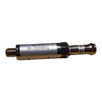
Mount the Outdoor Amplifier
Attach the outdoor am plier to the antenna mast about 12 inches
below the antenna (not included) with the supplied U-Bolt, nuts,
and washers.
n Note: Mount the o utdoor amplier w ith connections fa cing down
to avoid water entering t he amplier.
Connect the Antenna
1.
Use the coaxial cable with weatherboots to connect the outdoor
amplier’s IN terminal and the antenna.
Slide the weatherboots
snugly over the connectors.
2. Open the r ubber cover to set FM TRAP.
• ON to prevent FM signal interferen ce with your T V signal.
• OFF if connec ting to an FM radio.
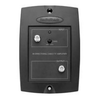
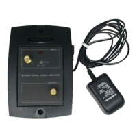
Connect the Amplifiers
1.
Connect your existin g coaxial cable (up to 200 f t
(60 m)) to the outdoor amplier’s OUT terminal.
2. Connect t he other end of your existing coaxial
cable to the indoor amplier’s INPUT terminal.
n Note: If necessar y, attach th e spare weatherboot
to your existin g coaxial cable to be conne cted to
the outdoo r amplier. Ask a sales associate for he lp
attachin g the weatherboot. Or, to attach it by yo urself,
cut o the F conn ector, slip the weath erboot onto the
cable, th en assemble the F connec tor back agai n.
Wall
Face
down
To
Antenna
Set FM TRAP
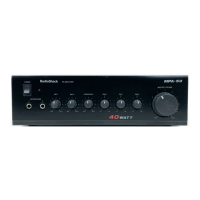
Adjust the Indoor Amplifier
• Turn GAIN towards
Min (counterclock wise) or Max (clockwise)
for
best reception. The optimum setting depends on the location,
cable lengths, an d number of connected devices.
• If the signal received is weak, set SIGNAL BO OSTER to
ON to amplify the signal a second time through the indoor
ampli er. Otherwise set SIGNAL BOOSTER to OFF.
TV or recei ver
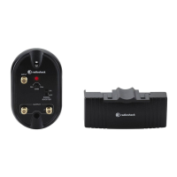
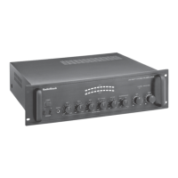
Set up the Indoor Amplifier
1.
Connect t he indoor amplier’s OUTPUT 1
terminal to your TV or recei ver using the supplied
6-foot coaxial cable without weatherboots.
2. Connect O UTPUT 2 to another TV or receiver. If
not using OUTPUT 2, cover it with the supplied
75-ohm terminator.
3. Connect t he AC adapter to the indoor amplier and
plug into a st andard power outlet. The LED lights.
n
Cautio n: The power ada pter must supply 12V DC and
deliver at leas t 200 mA . Its center tip must be set to positive
and its pl ug must t the indoor a mplier’s power jac k. Using
an adapter that d oes not meet these specicat ions could
damage the i ndoor amplie r or adapter.
Spare Weatherboot
F Connec tor
1500526_UG_EN_012314.indd 1-6 1/23/2014 4:02:32 PM