SECTION 4
TECHNICAL DESCRIPTION
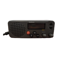
4.1 GENERAL
The VHF5200 can be considered as consisting of two major sections. They are:
l
The Control Circuitry (consisting of the front panel controls, the LCD display, control
CPU).
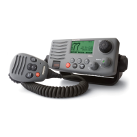
l The
Transmitter/Receiver/PLL
circuits.
4.2 THE CONTROL SECTION
The heart of the control section is the CPU, IC201, located on the main PCB.
The CPU controls all of the following items:
l
Controls the Squelch circuit by detecting a busy signal from the second IF circuit
IC5.
l
Generates a beep tone when a key is activated on the keyboard.
l
Mutes the transmitter modulation circuit when receiving.
l
Controls the output power of the transmitter High/Low.
l
Controls the dividing ratio N of the PLL circuit.
l
Switches On/Off the transmitter power.
l
Mutes AF audio.
l
Detects a weather alert signal (when in Monitor Mode).
l
Controls the LCD display.
4.3 THE
TRANSMITTERIRECEIVERPLL
SECTION
In reading through the following circuit descriptions, it may be helpful to refer to Figure 4-l Block
Diagram of the TX/RX/PLL circuits.
16
 Loading...