2.”
5
AUXILIARY
ALARM
Thl3
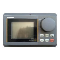
auxiliary alarm unit is waterproof and may
therefore be mounted in any position. The alarm
unit is supplied with a terminal block to connect a
two core interconnection cable to the course
computer.
A 22mm hole should be bored through
the mounting panel/deck to pass through the two
way connector block and interconnecting cable
(Fig. 13).
Finally, the alarm unit should be screwed into
position using the four self tapping screws
provided. A foam seal on the alarm mounting
flange will ensure a watertight joint to the
mounting surface.
Fig. 13
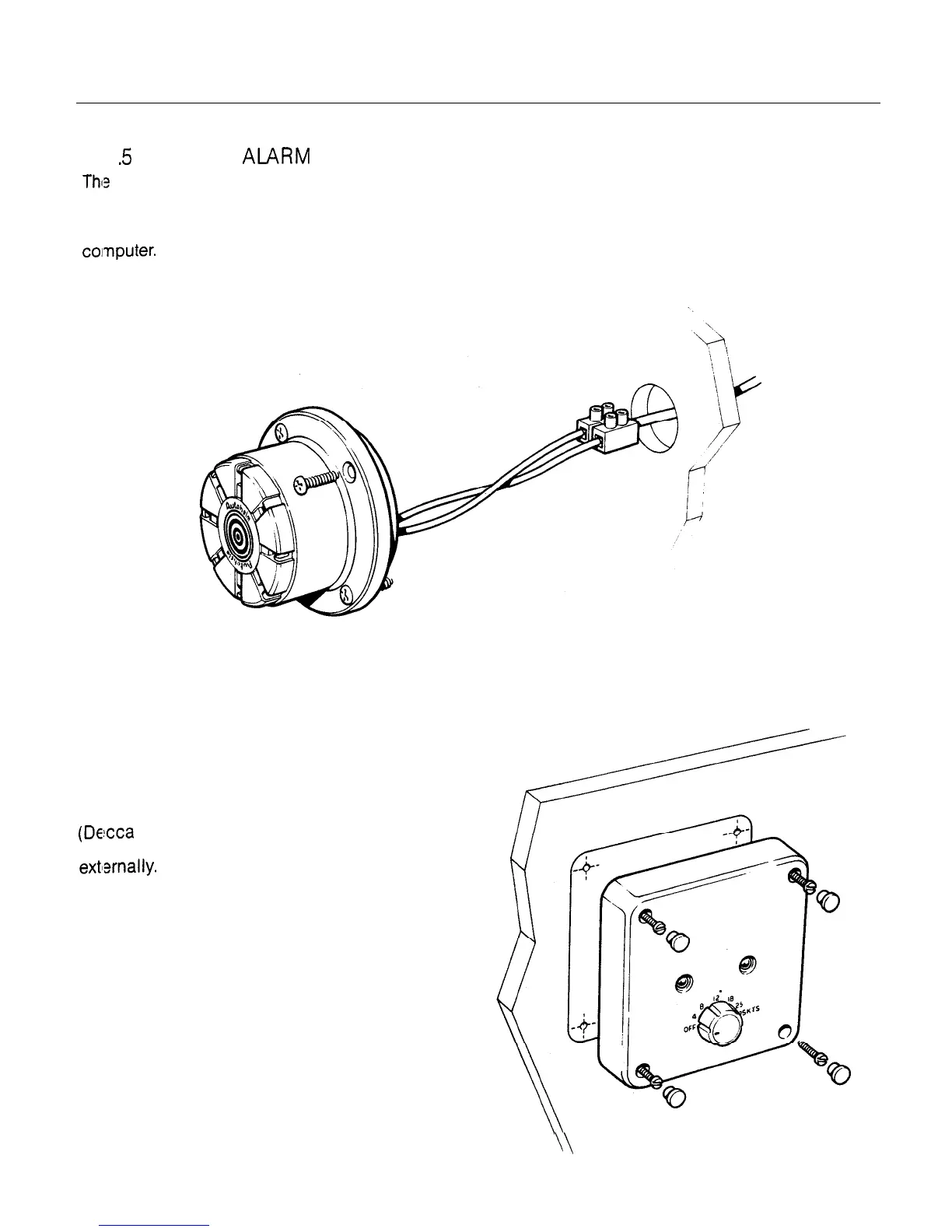
2.1.6 RADIO NAVIGATION INTERFACE
The radio navigation interface will normally be
mounted close to the radio navigation receiver
(Decca or Loran) in the navstation area. It IS
fully waterproof and if desired may be mounted
extlsrnally.
A printed template is provided to assist
marking out fixing hole positions and the hole
for the interconnecting cable. After threading
the interconnecting cable through the 20mm
dia. hole the interface unit is screwed into.
position using the four self-tapping screws
provided (Fig. 14).
Four blanking plugs are provided to conceal
the fixing screw recesses and these should be
firmly pressed into position to complete the
installation.
Fig. 14
\\
 Loading...