8 Wind Vane Service Manual
4. SLOWLY rotate the anemometer cups and check that the voltage between the yellow and black connections switches
between approximately 8 V and 3.2 V, twice during each rotation.
PCB
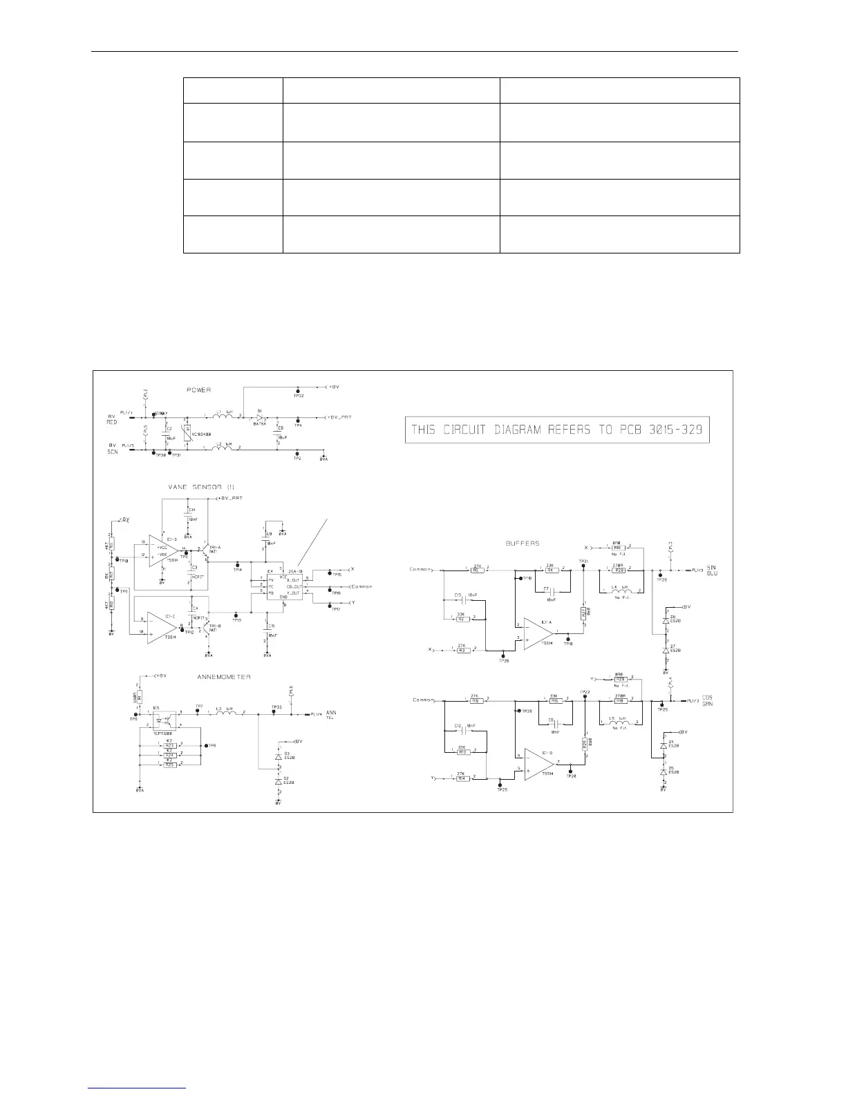
Circuit diagram
Vane direction Voltage between Blue & Black (sine signal) Voltage between Green & Black (cosine signal)
Pointing forward Half the supply voltage measured at step 2. Half the supply voltage as measured at step 2 plus at least
1 V but not more than 2 V
.
Pointing to starboard Half the supply voltage as measured at step 2 plus at
least 1 V but not more than 2 V.
Half the supply voltage measured at step 2.
Pointing aft Half the supply voltage measured at step 2. Half the supply voltage as measured at step 2 minus at
least 1 V but not more than 2 V.
Pointing to port Half the supply voltage as measured at step 2 minus
at least 1 V but not more than 2 V.
Half the supply voltage measured at step 2.
D6956-1 (From Drawing No. 4531-002G)
Do NOT attempt to replace or otherwise disturb IC4.
The correct physical alignment of this component is of
critical importance.
 Loading...