8
Description Location
Distance
in. (mm)
a. 3-1/2" (89 mm) thick
masonry walls without
ventilated air space
Back 9 (229)
Right 9 (229)
Left 9 (229)
Vent 5 (127)
Indoor Top 39 (991)
Outdoor Top Unobstructed
b. 1/2" (13 mm)insulation
board over 1" (25 mm)
glass ber or mineral
wool batts
Back 6 (152)
Right 6 (152)
Left 6 (152)
Vent 3 (76)
Indoor Top 30 (762)
Outdoor Top Unobstructed
c. 0.024 sheet metal over
1" (25 mm) glass ber
or mineral wool batts
reinforced with wire on
rear face with ventilated
air space
Back 4 (102)
Right 4 (102)
Left 4 (102)
Vent 3 (76)
Indoor Top 24 (610)
Outdoor Top Unobstructed
d. 3-1/2" (89 mm) thick
masonry wall with
ventilated air space
Back 6 (152)
Right 6 (152)
Left 6 (152)
Vent 6 (152)
Indoor Top 39 (991)
Outdoor Top Unobstructed
e. 0.024 sheet metal with
ventilated air space
Back 4 (102)
Right 4 (102)
Left 4 (102)
Vent 2 (51)
Indoor Top 24 (610)
Outdoor Top Unobstructed
f. 1/2" (13 mm) thick
insulation board with
ventilated air space
Back 4 (102)
Right 4 (102)
Left 4 (102)
Vent 3 (76)
Indoor Top 24 (610)
Outdoor Top Unobstructed
g. 0.024 sheet metal with
ventilated air space over
0.024 sheet metal with
ventilated air space.
Back 4 (102)
Right 4 (102)
Left 4 (102)
Vent 3 (76)
Indoor Top 24 (610)
Outdoor Top Unobstructed
h. 1" (25 mm) glass ber
or mineral wool batts
sandwiched between two
sheets 0.024 sheet metal
with ventilated air space
Back 4 (102)
Right 4 (102)
Left 4 (102)
Vent 3 (76)
Indoor Top 24 (610)
Outdoor Top Unobstructed
Derived from National Fuel Gas Code, Table 10.2.3
Table C. Reduction of Clearances to Protected Surfaces
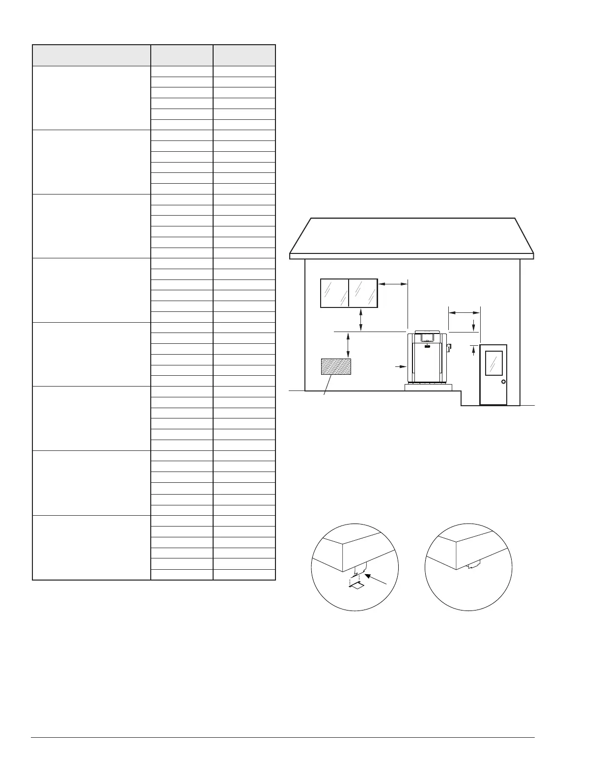
Heaters must not be installed under an overhang of less
than three 3' (0.9 m) from the top of the heater. Three sides
must be open in the area under the overhang. Roof water
drainage must be diverted away from the heaters installed
under overhangs with the use of gutters.
For U.S. installations, the point from where the ue
products exit the heater must be a minimum of 4' (1.2 m)
below, 4' (1.2 m) horizontally from, or 1' (0.3 m) above any
door, window or gravity inlet into any building. The top
surface of the heater shall be at least 3' (0.9 m) above
any forced air inlet, or intake ducts located within 10' (3 m)
horizontally.
For Canadian installations, pool heaters shall not be
installed with the top of the vent assembly within 10' (3 m)
below, or to either side, of any opening into the building.
Refer to the latest revisions of CAN/CSA-B149.
A minimum of 6' (1.8 m) is required from the heater to an
inside corner wall for proper outdoor venting.
For installations in Florida and Texas, that must comply
with the Florida or Texas Building Code, follow the directions
shown in Figure 7 for the installation of hurricane tie-down
brackets for all models.
Forced Air Inlet
4' (1.2 m)
Minimum
3' (0.9 m)
Minimum
10' (3 m)
Minimum
1' (0.3 m)
Minimum
4' (1.2 m)
Minimum
4' (1.2 m)
Minimum
Figure 3. Clearances
Pagoda Top Installation
1. Insert tabs into keyhole (4 places). See Figure 4,
detail A.
2. Snap tabs into keyholes so as not to pull out. See
Figure 4, detail B.
OUTDOOR TOP
(SHIPPED LOOSE WITH HEATER)
DETAIL A DETAIL B
Figure 4. Outdoor Top Installation
Indoor Heater Installation
The heater is also design-certied for indoor installation
when equipped with the approved drafthood.
 Loading...