1
F O R M
Evergreen
®
OM
Outdoor Fan Motor
Installation Guide
G0038E
Revised
September 2019
Regal Beloit America, Inc.
1325 Heil Quaker Blvd.
LaVergne, TN 37086
Customer Service: 866 503 8566
thedealertoolbox.com
CAUTION indicates a hazardous situation that, if not avoided,
could result in minor or moderate injuries.
• Periodic inspections should be performed. Failure to perform
proper maintenance could result in premature product failure.
• Installation and service of this motor should be performed only
by trained and qualified service technicians familiar with the
Evergreen
®
OM motor and the HVAC systems into which it will
be installed.
WARNING indicates a hazardous situation that, if not avoided, could
result in death or serious injury.
• Read and follow all instructions carefully.
• Disconnect and lock out the main power from the unit being
serviced before installing the Evergreen
®
OM motor. It is also a
good practice to confirm that the power is disconnected with a
voltmeter.
• Do not operate equipment without guards in place.
• Improper installation, adjustment, alteration, service,
maintenance, or use could cause explosion, fire, electrical shock,
or other conditions. Consult a qualified installer, service agency,
or your distributor or branch for information or assistance.
The qualified installer or agency must use the supplied or
recommended parts when installing or servicing this product.
• After installing the Evergreen
®
OM motor, it is the responsibility
of the installing technician to verify the HVAC system matches
the manufacturer’s requirements for proper operation, capacity,
efficiency and safety.
Page 1 6301 & 6303 mechanical installation
Page 1-2 6303R (Remote Mount) mechanical installation
Page 3 6301, 6303 & 6303R (Remote Mount) electrical connections
Page 4 Specifications, diagnostics and warranty information
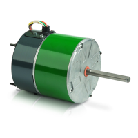
Evergreen
®
OM Models 6301 & 6303
Mechanical Installation
Install the motor using the extended clamp-bolts or belly band mount.
Changing Rotation
From the factory, the motor will be set up for CCW rotation, as viewed from
lead end.
The Yellow wire connected thru the 2 pin connector to the Violet wire and the
Orange wire connected thru the 2 pin connector to the Brown wire.
To change the rotation from CCW to CW:
• Disconnect the 2 pin connector and rotate it 180° so the Yellow wire is
connected to the Brown wire thru the 2 pin connector and the Orange
wire is connected to the Violet wire thru the 2 pin connector.
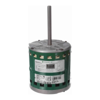
Evergreen
®
OM Models 6303R (Remote Mount)
Mechanical Installation
The hardware described in the mounting instructions for the motor and the
motor control are located in the parts bag, in the box with the motor, with the
exception of the four (4) mounting screws in the side of the motor.
There are two components to install, the motor and the motor control.
There is a break point in the umbilical cord between the motor control and
the motor comprised of four quick connect terminals. These terminals can be
separated to make it easier to install each component and for routing of the
umbilical cord through the wiring conduit if applicable.
This installation guide covers Evergreen
®
OM models 6301, 6303 and 6303R (Remote Mount).
Yellow
Orange
CCW (Factory)
Violet
Brown
Yellow
Orange
CW
Brown
Violet
Rotation Connector
CAUTION: Secure all wires, including the Rotation Connector,
out of the path of the fan blade before starting the motor!
Motor
Umbilical Cord
Line Voltage
Harness
Motor Control