TABLE OF CONTENTS
GENERAL INFORMATION ....................................................................1
Applicability ..............................................................................1
Important Safety Information .................................................................1
POWER VENT KITS .........................................................................2
Voltage ..................................................................................2
Kit Selection ..............................................................................2
Venter Assembly ..........................................................................3
Control System ............................................................................4
Venter Adapter ............................................................................4
Power Venter Sequence of Operation ..........................................................5
KIT INSTALLATION .........................................................................5
VENTING ..................................................................................9
Specific Venting Requirements ...............................................................9
Connecting Vent Cap To Double-Wall (Type B) Vent Terminal Pipe ..................................12
Connecting Single-Wall Vent Run to Double-Wall (Type B) Vent Terminal Pipe .........................12
OPERATIONAL TESTING ...................................................................12
REPLACEMENT PARTS .....................................................................13
Revision: X-CA1,2,3,4 (01-22) 136958-A
POWER VENT KIT INSTALLATION FOR DUCT FURNACES
Supersedes: X-CA1,2,3,4 (11-21) 136958-A
OPTIONS CA1, CA2, CA3, AND CA4 FOR MODEL X
AND OBSOLETE MODELS (H)CX, DX, (H)XE, AND (H)CXE
GENERAL INFORMATION
This optional power venter is a motorized vent exhauster designed to permit the installation of a gravity-vented heater
in an area of negative pressure up to 0.15 IN WC or where horizontal venting is required.
Applicability
NOTE: Models with the H prefix are standard and are not listed separately throughout this manual.
The venter assembly in this instruction form is designed to be installed only on the following equipment:
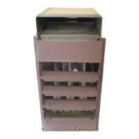
• Models X/DX/HX and CX/HCX: duct furnace
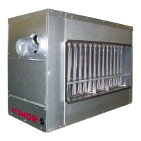
• Models XE/HXE and CXE/HCXE: packaged duct furnace and blower
• Models XL/CXL and XLB/CXLB: fan and blower type unit heaters (power venter cannot be installed on model
XLB/CXLB units in sizes 030–105 when equipped with an optional blower cabinet)
Important Safety Information
• Refer to the installation manual provided with the unit for important safety information.
• Pay attention to all dangers, warnings, cautions, and notes highlighted in this manual. Safety markings should not
be ignored and are used frequently throughout to designate a degree or level of seriousness.
⚠ DANGER ⚠
Improper installation, adjustment, alteration, service, or maintenance can cause property damage,
injury, or death. Read the installation, operation and maintenance instructions thoroughly before
installing or servicing this equipment.