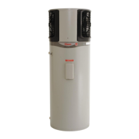
HEAT PUMP AND TANK ASSEMBLY
19
13. Power Cable Connection: Connect the four (4) pin power cable plug to
the connector at the top of the control board.
Ensure the plug fully engages the locking feature on the connector.
14. Cable Tie Power Cable: Position the power cable firmly against the
outside lower left hand side of the control board chassis and cable tie in
position. The cable tie is to fit in the recess at the front edge of the chassis
and through the adjacent slot.
15. Electrical Cover: Replace the electrical cover, engaging the bottom of the
cover into the slots on the supporting bracket.
Secure at the side with the mounting screw.
16. Condensate Drain: Install a drain line to the condensate drain to carry the
discharge clear of the water heater. Refer to “Condensate Drain” in the
“Connections – Plumbing” section in the Owner‟s Guide and Installation
Instructions supplied with the storage tank.
17. Water Connections: Connect the cold water supply and the hot water
pipe work to the water heater.
Connect the temperature pressure relief valve and its drain line.
Refer to “Connections – Plumbing” in the Owner‟s Guide and Installation
Instructions supplied with the storage tank.
18. Water Supply: Turn on the cold water supply and fill the water heater.
Check the pipe work and the inlet and outlet connection points of the
flexible hoses for leaks.
Refer to “To Fill And Turn On The Water Heater” on page 22, however the
electrical supply should not be switched on at this stage.
19. Air Louvre Attachment: Replace the two air louvres, ensuring the longer
skirt of the louvre is orientated to the bottom and re-fit all twelve (12)
louvre attachment screws.
20. Electrical Connection: Refer to “Connections – Electrical” on page 20
and in the Owner‟s Guide and Installation Instructions supplied with the
storage tank.
21. Commissioning: Refer to “Commissioning” on page 22 and in the
Owner‟s Guide and Installation Instructions supplied with the storage tank.
 Loading...