28
Our reliability department has identified
open limits in hot attics to be a potential
field issue with residential gas furnaces.
Because of this, residential gas furnace
operation will be modified on both
single-stage direct-spark ignition and all
hot-surface ignition I.F.C.’s (Integrated
Furnace Controls).
As a consequence, some trouble-
shooting approaches should be
modified. In particular is a common field
method to test for a properly functioning
limit or limit circuit. The procedure is to
disconnect the limit wires from the
limit(s) during steady “on” or idle (no call
for heat, cool or continuous fan present).
When this was done in the past, the
indoor blower and inducer would turn on
immediately. However, with the new
I.F.C.’s, this will no longer be the case.
Instead, the unit will do nothing. The
reason is that the system is ignoring the
limit circuit in case of an accidental trip
in a hot attic.
There are a couple of alternate
approaches to testing the limit(s) or the
limit circuit in the newer residential gas
furnace equipment:
1. To test the limit itself, remove the
wires and check with an ohmmeter.
Under normal conditions, the meter
should read zero ohms, indicating
that the limit is closed and is not too
hot or failed in the “open” state.
2. Remove the limit wires (simulating
an open limit) during pre-purge of a
heat call. During this time, the
indoor blower should turn on and a
fault code three (three blinks)
should flash (inducer is already
running at this time). The unit will
not light until the limit circuit is
closed.
3. Remove the limit wires (simulating
an open limit) during steady-state
heat (IE: flame present and indoor
blower motor is running). The flame
should extinguish immediately and
a fault code three (three blinks) will
flash. The indoor blower and
inducer should continue running
until the limit is closed.
4. To test the circuit to the limit, use
an ohmmeter to check the wires
from one limit to the next limit in the
chain or to the I.F.C. (consult the
wiring diagram(s)). Remember that
good wire and connections should
read zero ohms (or very close).
SETTING BLOWER TIMINGS
The UT Electronic Controls control
boards have four quick connect
terminals for connecting the motor
speed leads. These are:
1. FAN SPEED* — motor runs on this
speed when the thermostat is in the
“FAN” position.
2. COOL — connect desired cooling
speed.
3. HEAT — connect desired heating
speed.
4. HEAT/COOL* — connect desired
speed when heating and cooling
speed are the same.
*NOTE: These taps are not available on
UT Electronic Controls 1097-200.
DO NOT CONNECT ANY MOTOR
SPEEDS TO “HEAT” OR “COOL” IF
YOU USE THE “HEAT/COOL”
TERMINAL. DOING SO WILL
DAMAGE THE BLOWER MOTOR.
UNUSED MOTOR WIRE TAPS MUST
BE CONNECTED TO PARKING
TERMINALS M1 AND M2 OF THE
IFC, OR PROPERLY INSULATED.
5. If heating and continuous speed
are the same, jump across “FAN”
and “HEAT” terminals.
NOTE: This does not apply to UT
Electronic Controls 1097-200 models
because the heat tap functions as the
continuous fan tap as well.
See Figures 21 and 22 for instructions for
setting the blower “OFF” timings.
GAS FURNACE (DIRECT
DRIVE) INSTRUCTIONS FOR
CHANGING BLOWER SPEED
DISCONNECT THE ELECTRICAL
SUPPLY TO THE FURNACE BEFORE
ATTEMPTING TO CHANGE THE
BLOWER SPEED. FAILURE TO DO
SO CAN CAUSE ELECTRICAL
SHOCK RESULTING IN SEVERE
PERSONAL INJURY OR DEATH.
The blower motor is wired for blower
speeds required for normal operation
as shown.
If additional blower speed taps are
available (leads connected to “M1” and
“M2” on the electronic control), speeds
may be changed if necessary to fit
requirements of the particular
installation. Reconnect the unused
motor leads to “M1” or “M2.” Check
motor lead color for speed designation.
Heating speeds should not be reduced
where it could cause the furnace air
temperature to rise to exceed the
maximum outlet air temperature
specified for the unit.
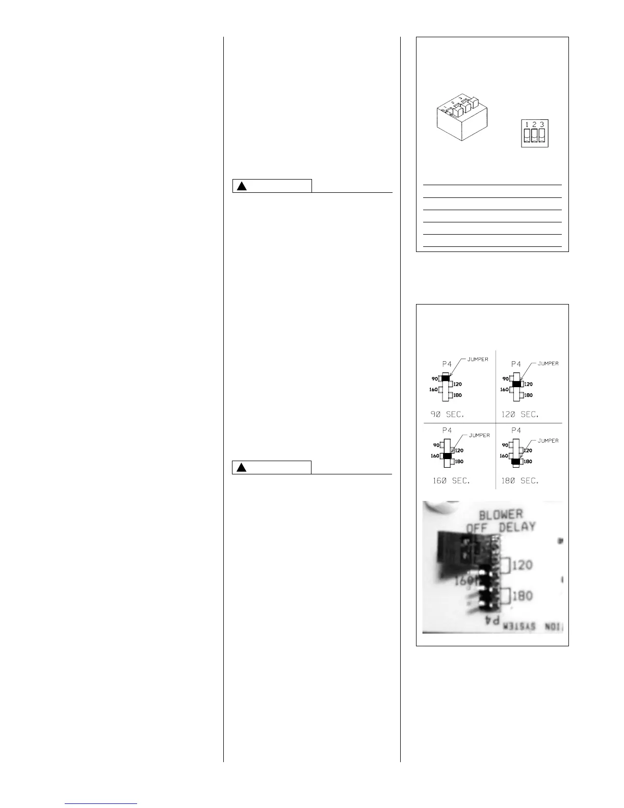
FIGURE 21
UT Electronic Controls 1028-928
BLOWER OFF TIMINGS
OFF TIME SWITCH 1 SWITCH 2
90 SEC. OFF ON
120 SEC. OFF OFF
160 SEC. ON OFF
180 SEC. ON ON
TWINSINGLE
NOTE: SWITCH 3 IS USED FOR
TWINNING APPLICATIONS.
ON
OFF
I402
WARNING
!
CAUTION
!
FIGURE 22
UT Electronic Controls 1097-200
BLOWER OFF TIMINGS
IMPORTANT: Always check air
temperature rise after changing the
heating speed for any reason or if there
are any changes to the duct system.
 Loading...