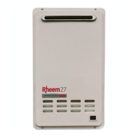
TM049 27L Continuous Flow Service Instructions
REV AL – Issued April 2019
This document is stored and maintained electronically by Rheem Technical Support. All printed copies are deemed “uncontrolled”.
OPERATIONAL FLOW CHARTS
About the Operational Flow Charts
The Operational Flow Charts provide information on the start up sequence and, in the event
a failure occurs at any point of the start up sequence, what error code will be displayed.
Error codes are displayed via the red LED mounted on the PCB. If fitted, the remote
controllers will also display error codes.
The Sequence Number Table below indicates the section of the operational sequence
(boxed numbers on the operational flow chart) where the fault occurred.
Circled numbers, adjacent to the component or function, indicate the diagnostic test point
required to diagnose the fault. Refer to the table on page 39.
By locating the error code in the diagnosis charts the component/s or fault can be quickly
identified and tested using the diagnostic procedures outlined in this manual.
Notes and Abbreviations used in the Operational Flow Charts
Proportional Gas Flow Regulating Valve
Gas Inlet Solenoid Valve (SV0)
In Use Indicator (Combustion Indicator)
Stepping gas rate change sequence by solenoid
Sequence Number Table
Operational Flow Chart Section
Test Equipment
A list of test equipment which will assist in conducting diagnostic procedures is provided
below. This equipment is available from Rheem Service Spare Parts Department.
Flame detection simulator
Flame sensor current (uA) detection kit
Probe to alligator clip kit

 Loading...