EasyManuals Logo

Rheem 862 27 Series User Manual

Rheem 862 27 Series
84 pages
To Next Page IconTo Next Page
To Previous Page IconTo Previous Page
Page #39 background imageLoading...
Page #39 background image
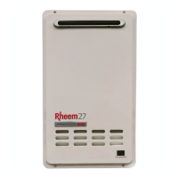
TM049 27L Continuous Flow Service Instructions
REV AL Issued April 2019
This document is stored and maintained electronically by Rheem Technical Support. All printed copies are deemed “uncontrolled”.
39
DIAGNOSTIC TEST POINTS
Measurement Point
Normal Value
Point to Check
No.
Connection
Wire
Colour
1
A
BL1 BR4
216~264 VAC
Main Power.
2
T
W1 W2
50k 500k
Over Heat Limiter.
3
S
BR1 BK2
2 5 VDC (pulse)
>1310 pulses/minute
Water Flow Sensor pulse signal.
(Only when water is flowing)
R3 BK2
11 17 VDC
Water Flow Sensor.
4
J
BL4 W6
(outdoor)
144 192 VDC
Fan Motor has proper voltage.
BK4 R6
(indoor)
R3 BL4
(outdoor)
12 - 18 VDC
Fan Motor has proper voltage.
W3 BK4
(indoor)
Y1 BL4
(outdoor)
4 10 VDC (Pulse)
>4800 pulses/minute
Fan Motor producing a regular pulse.
BL1 BK4
(indoor)
5
P
W6 BK3
Refer to thermistor
resistance chart on
following page.
Cold water inlet thermistor.
6
P
Y5 BK3
Heat exchanger thermistor.
7
P
R4 BK3
Hot water outlet thermistor.
17
P
BL7 BK3
Ambient air thermistor.
8
U
W1 GND
0.3 100VAC
Flame rod not detecting flame.
14
1 100VAC
Flame rod detecting flame.
9
P
R1 BK2
1.5 14 VDC
PGFR (Proportional Gas Flow
Regulating Valve)
40 80Ω
10
W
Y1 BK8
75 100 VDC
GISV 0 (Gas Inlet Solenoid Valve 0)
(Primary fuel inlet to gas valve)
0.8 2.4k
11
G
R1 R4
90 - 110VAC
Igniter
12
W
W2 BK8
75 100VDC
Solenoid valve (SV1)
(Fuel to ODS and front right burner)
0.8 2.4k
13
W
R5 BK8
75 100VDC
Solenoid valve (SV2)
(Fuel to back right burner)
0.8 2.4k
18
W
BL6 BK8
75 100VDC
Solenoid valve (SV3)
(Fuel to left side burner)
0.8 2.4k
15
N
W2 BK8
8 16VDC
Water volume control motor has
proper voltage.
R7 BK8
8 16VDC
Water volume control motor has
proper voltage.
GR6 BK8
Less than 1VDC (Limiter
on) 4 6VDC (Limiter Off)
Water volume control motor position
switch is normal.
22
M
W2 BK8
8 16VDC
Water bypass control motor has
proper voltage.
R7 BK8
8 16VDC
Water bypass control motor has
proper voltage.
GR6 BK8
Less than 1VDC (Limiter
on)
4 6VDC (Limiter Off)
Water bypass control motor position
switch is normal.

Questions and Answers:

Question and Answer IconNeed help?

Do you have a question about the Rheem 862 27 Series and is the answer not in the manual?

Rheem 862 27 Series Specifications

General IconGeneral
BrandRheem
Model862 27 Series
CategoryWater Heater
LanguageEnglish

Related product manuals