Home
Ricoh
All in One Printer
D147
Ricoh D147 User Manual
5
of 1
of 1 rating
2375 pages
Give review
Manual
Specs
To Next Page
To Next Page
To Previous Page
To Previous Page
Loading...
Fans
/Fi
l
ter
s
D146/D147/
D148/D149/
D150
4-
158
SM
4.1
8.3
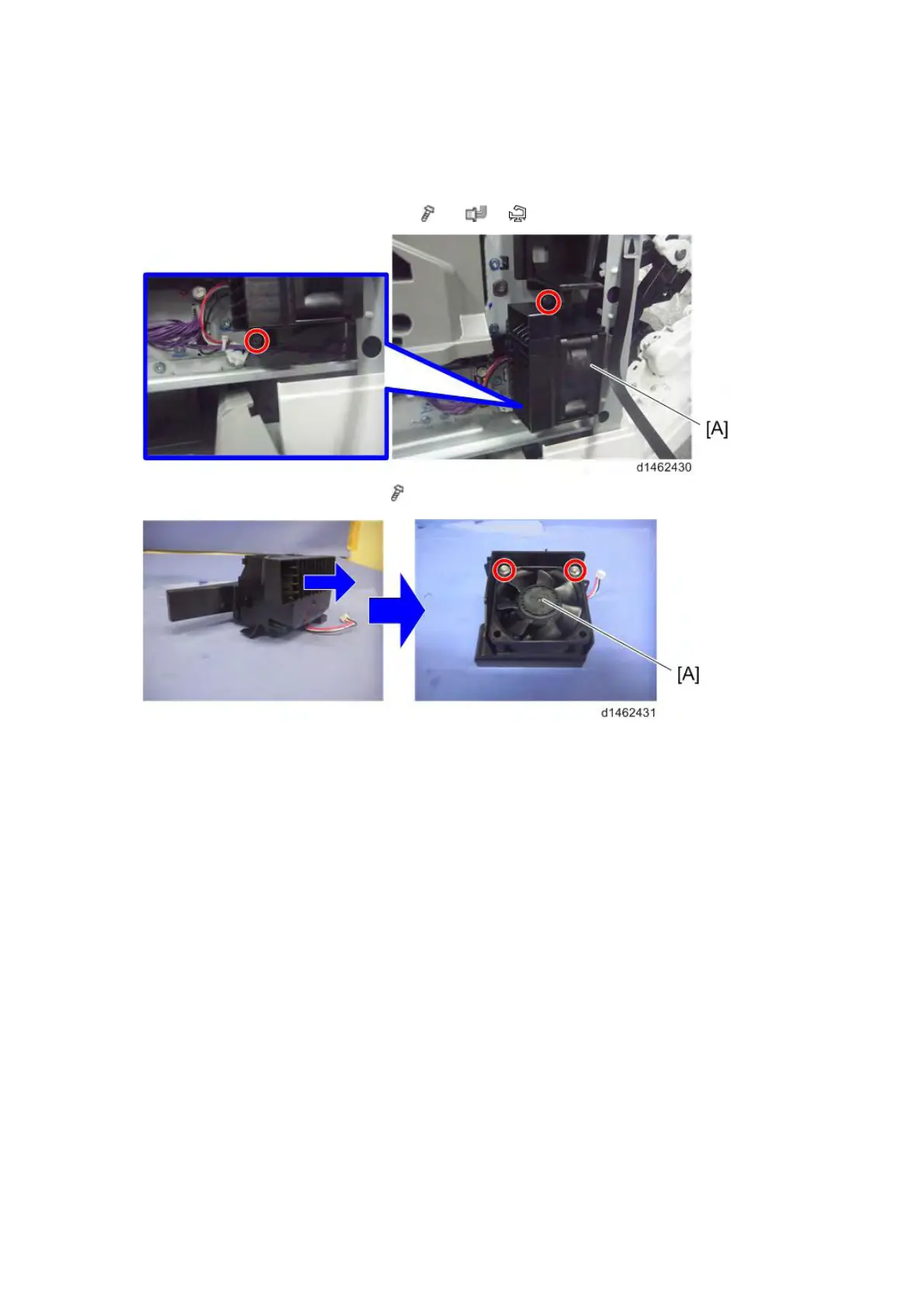
DEVEL
OPMENT INTAKE F
AN
/RIGH
T
1.
Inner
low
er c
ov
er
(pag
e
4-
18
"
Inner
Low
er
C
over
")
2.
Dev
elopm
ent i
ntake f
an/R
ig
ht uni
t [
A
] (
×
2,
×
1,
×1)
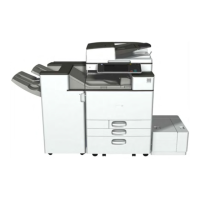
3.
Dev
elopm
ent i
ntake f
an/R
ig
ht [
A] (
×2)
451
453
Table of Contents
Table of Contents
6
Laser Safety
21
Product Information
24
Product Overview
26
Component Layout
26
Scanner Unit
26
Product Information
26
Laser Exposure Unit
28
Image Transfer Unit
29
Pcdu
30
Toner Supply / Waste Toner Bottle
31
Paper Feed Unit
32
Duplex Unit
33
By-Pass Unit
34
Fusing Unit
35
Paper Transfer / Paper Exit
36
Air Flow
37
Drive Unit
38
Board / Switch
39
Paper Path
40
Drive Layout
43
Machine Codes and Peripherals Configuration
45
Diagram
45
D146/D147 Options (Mainly North America)
45
D146/D147 Options (Mainly Europe and Asia)
48
D148D149 Options (Mainly North America)
51
D148/D149 Options (Mainly Europe and Asia)
54
D150 Options (Mainly North America)
57
D150 Options (Mainly Europe and Asia)
60
Specifications
63
Guidance for those Who Are Familiar with Predecessor Products
64
Differences from Predecessor
64
Scan, LD Unit, Paper Feed Unit
64
Duplex, Driving, Main Frame
65
Pcdu
65
Toner Supplement, Image Transfer
66
Fusing
67
Electrical Component
68
Important Notice for Machine
69
Installation
70
Installation Requirements
72
Environment
72
Machine Level
73
Machine Space Requirements
73
Machine Dimensions
74
Power Requirements
75
Input Voltage Level
75
Main Machine Installation
76
Installation Flow Chart
76
Accessory Check
77
Installation Procedure
78
Removal of Packing Materials and Shipping Retainers / Removal of PCDU Seal
78
For Machines with Preinstalled SPDF: Removal of Protective Sheet
85
Toner Bottle Installation
85
Attaching Paper Output Tray Parts
87
Attaching the Decals
87
Connecting the Power Cord
87
Image Quality Test / Settings
88
Image Quality Test
88
Checking the Copy Image with the Test Chart
88
Paper Setting
88
Security Function Installation
88
Moving the Machine
96
Transporting the Machine
96
Main Frame
96
Paper Feed Unit Pb3160
97
Accessory Check
97
Installation Procedure
97
Paper Feed Unit Pb3150
101
Accessory Check
101
Installation Procedure
101
Lcit Pb3170
104
Accessory Check
104
Changing the Paper Size
107
Accessory Check
110
Installation Procedure
110
Lcit Rt3030
110
Changing the Paper Size
114
Caster Table Type M3
116
Accessory Check
116
Installation Procedure
116
Platen Cover Pn2000
118
Accessory Check
118
Installation Procedure
119
Ardf Df3090
121
Accessory Check
121
Installation Procedure
122
When Feeding Thin Paper
125
Spdf Df3080
126
Accessory Check
126
Installation Procedure
127
Attaching the SPDF
127
Attaching the Sub IPU / Replacing the BCU
130
Set Serial Number on New BCU
137
Adjust SP Settings
137
Bridge Unit Bu3070
139
Accessory Check
139
Installation Procedure
139
Bin Tray Bn3110
144
Accessory Check
144
Installation Procedure
144
Internal Shift Tray Sh3070
150
Accessory Check
150
Installation Procedure
150
Side Tray Type M3
154
Accessory Check
154
Installation Procedure
155
Booklet Finisher Sr3170 (D688)/ Finisher Sr3160 (D689)
158
Auxiliary Tray
164
Punch Unit Pu3060
165
Accessory Check
165
Installation Procedure
166
Booklet Finisher Sr3150 / Finisher Sr3140
175
Installation Procedure
176
Punch Unit Pu3050
182
Accessory Check
182
Installation Procedure
182
Internal Finisher Sr3130
192
Accessory Check
192
Installation Procedure
193
Punch Unit Pu3040
201
Installation Procedure
207
Key Counter Bracket Type M3
207
Installation Procedure
209
Optional Counter Interface Unit Type a
209
Key Counter
209
Internal Options
211
List of Slots
211
D148/D149/D150
211
D146/D147
212
Ieee 1284 Interface Board Type a
213
Installation Procedure
215
Ieee 802.11A/G/N Interface Unit Type M2
215
Accessory Check
215
Attaching the Boards
216
Attaching the Antenna
217
Settings
217
Check the Connection of the Wireless LAN Interface
217
Bluetooth Interface Unit Type D
219
Accessory Check
219
Installation Procedure
221
File Format Converter Type E
221
Accessory Check
221
Data Overwrite Security Unit Type H (D377)/ I (D362)
223
Overview
223
Component List
223
Before You Begin the Procedure
224
Seal Check and Removal
225
Installation Procedure
226
Configuring "Auto Erase Memory
227
Customer)
227
Copy Data Security Unit Type G
230
Accessory Check
230
Installation Procedure
230
Settings (to be Done by the User)
232
Equipment Administrator Settings
232
Imageable Area Extension Unit Type M3
233
When You Forgot to Change the SP
236
Searchable Pdf Function Outline
237
Ocr Unit Type M2
237
Installation Procedure
238
Recovery Procedure
240
Sd Card Option
241
Sd Card Slots
241
List of Slots Used
241
Sd Card Appli Move
242
Overview
242
Move Exec
243
Undo Exec
245
Browser Unit Type M4/M3
246
Accessory Check
246
Installation Procedure
246
To Update EXJS
249
When Checking the Version of EXJS
251
Browser Unit Uninstallation Procedure
251
Settings
252
Browser Default Setting
252
Sd Card for Netware Printing Type M4/M3
253
Accessory Check
253
Installation Procedure
263
Accessory Check
269
Installation Procedure
269
Accessory Check
274
Installation Procedure
274
Installation Procedure
277
Accessory Check
277
Preventive Maintenance
281
Pm Parts Settings
283
Replacement Procedure of the Pm Parts
283
After Installing the New Pm Parts
284
Preparation before Operation Check
285
Operation Check
285
Image Quality Standards
286
Resolution
286
Color Shift
286
Magnification Ratio Error Margin
287
Magnification Ratio Error Margin Deviation
288
Pitch Error Margin
288
Perpendicularity
288
Linearity
289
Parallelism
289
Missing Image Area (D135/D136)
290
Margin Position
290
Paper Transfer Quality Standards
291
Registration
291
Skew
291
Exposure Glass
291
Adf
292
Replacement and Adjustment
293
Notes on the Main Power Switch
295
Push Switch
295
Characteristics of the Push Switch (DC Switch)
295
Shutdown Method
296
Forced Shutdown
296
Beforehand
297
Special Tools
298
Exterior Covers
299
Front Cover
299
Controller Cover
300
Upper Left Cover
301
Left Rear Cover
302
Left Cover
302
Rear Cover
304
Rear Right Cover
305
Rear Lower Cover
305
Scanner Rear Cover
305
Scanner Rear Cover (Small)
306
Right Rear Cover
306
Right Upper Cover
307
Main Power Switch Cover
307
Waste Toner Cover
308
Reverse Tray
308
Paper Exit Tray
309
Paper Exit Cover
309
Paper Exit Lower Cover
310
Paper Exit
311
Inner Upper Cover
312
Inner Lower Cover
312
Controller Unit
313
Operation Panel
313
Board a
314
Board B
315
Board C
316
Lcd Panel
316
Lcd
317
Notes When Replacing the LCD
317
Replacement Procedure
319
Scanner Unit
321
Scanner Exterior
321
Scanner Upper Cover
321
Scanner Right Cover
321
Scanner Front Cover
322
Scanner Left Cover
322
Exposure Glass
323
Exposure Lamp (Led)
324
Scanner Motor
325
Lens Block
327
Original Size Sensor
328
Sio
328
Scanner Hp Sensor
329
Df Position Sensor
330
Adjusting the Scanner Wire
331
Scanner Wire (Front)
331
Scanner Wire Assembly (Front Side)
333
Scanner Position Adjustment
335
Scanner Wire (Rear)
336
Scanner Wire Assembly (Rear Side)
339
Modifying the Scanner (Contact/Contactless) When Using Ardf
339
Procedure for the ADF
339
Procedure for the Scanner
342
Modifying the Scanner (Contact/Contactless) When
342
Procedure for the SPDF
342
Procedure for the Scanner
344
Laser Unit
345
Before Replacement
346
Removing
346
Installing a New Laser Unit
347
Adjustment after Replacing the Laser Unit
348
Polygon Motor
349
Adjustment after Replacing the Polygon Motor
350
Imaging Temperature Sensor (Thermistor)
350
Pcdu
351
Notes When Replacing a Pcdu
351
D146/D147/ D148
351
D149/D150
351
Pcdu
352
Adjustment before Replacing the PCDU
352
Replacement
353
Pcu/Development Unit
355
Before Replacing a PCU or Development Unit
355
Replacement
355
Precautions When Joining the PCU and the Development Unit
357
Check Procedure after Replacing
357
Waste Toner
358
Replacement
358
Adjustment after Replacing
358
Image Transfer Unit
359
Image Transfer Belt Unit
359
Adjustment before Replacing the Image Transfer Belt Unit
359
Replacement
359
Image Transfer Cleaning Unit
362
Adjustment before Replacing the Image Transfer Cleaning Unit
362
Replacement
362
Image Transfer Belt
364
Adjustment after Replacing the Image Transfer Belt
366
Paper Transfer Roller
367
Paper Transfer Roller Unit
367
Adjustment before Replacing the Paper Transfer Roller Unit
367
Replacement
367
Paper Transfer Exit Sensor
370
Tm (ID) Sensor
370
Before Replacing the TM(ID) Sensor
370
Replacement Procedure
372
Adjustment after Replacing the TM(ID) Sensor
373
Temperature and Humidity Sensor
374
Drive Unit
375
Overview
375
Paper Feed Motor
376
Transport Motor
376
Transfer Motor Unit
377
Imaging Drive Unit
379
Pcu Motor: Cmy
380
Development Motor: Cmy
380
Development Motor: Black
381
Pcu: Black / Image Transfer Motor
381
Registration Motor
381
Fusing Motor
382
Paper Exit / Pressure Release Motor
382
Duplex Entrance Motor
383
Toner Transport Motor
384
Sub Hopper
384
Toner End Sensor
388
Toner Bottle Drive Motor
389
ID Chip
391
Fusing Unit
393
Replacement
393
Fusing Entrance Guide Plate
394
Cleaning the Fusing Entrance Guide Plate
394
Fusing Exit Guide Plate
395
Cleaning the Fusing Exit Guide Plate
395
Fusing Upper Cover
396
Fusing Lower Cover
396
Fusing
397
Fusing Rear Cover
397
Heating Sleeve Belt Unit
398
Replacement
398
Pressure Roller
399
Adjustment before Replacing the Pressure Roller
399
Replacement
399
Thermostat Unit
401
Nc Sensor Unit
402
Fusing Thermistor
402
Fusing Thermopile Unit
403
Pressure Roller Hp Sensor
403
Fusing Shield Position Sensor
404
Fusing Shield Drive Motor
405
Paper Exit
406
Paper Exit Unit
406
Paper Exit Switching Solenoid
406
Paper Exit Sensor
407
Reverse Sensor
408
Paper Exit Full Sensor
409
Reverse Motor
409
Fusing Exit Sensor
410
Paper Feed
411
Paper Feed Unit
411
1St Paper Feed Unit
411
2Nd Paper Feed Unit
412
Paper Dust Collection Unit
414
Pick-Up Roller, Paper Feed Roller, Separation
414
Roller, Torque Limiter
414
Paper Feed Solenoid
416
Paper Feed Sensor
417
Vertical Transport Sensor
418
Limit Sensor
419
Paper End Sensor
419
Registration Sensor
420
By-Pass Tray Unit
421
By-Pass Tray
421
By-Pass Paper End Sensor
423
By-Pass Pick-Up Roller
424
By-Pass Paper Feed Roller
424
By-Pass Separation Roller
425
Torque Limiter
425
By-Pass Tray Side Fence (D150 Only)
426
Duplex Unit
428
Duplex Unit
429
Duplex/By-Pass Motor
430
Duplex Entrance Sensor
431
Duplex Jam Processing Led
433
Duplex Exit Sensor
433
Double Feed Sensor (D150 Only)
434
Electrical Components
436
Overview
436
Printed Circuits/Parts Inside the Controller Box
436
Printed Circuits Behind the Controller Box
437
Printed Circuit/Parts Inside the Power Box
437
Printed Circuits Behind the Power Box
438
Ipu Sub (Spdf Only)
438
Ipu
439
Bcu
441
Replacing the NVRAM (EEPROM) on the BCU
441
Controller Board
442
Nvrams on the Controller Board
443
Hdd
444
Adjustment after Replacement
445
Cpu Cooling Fan
445
Imaging Iob
445
Hvp_Tts
446
Psu (Ac Controller Board)
447
Psu (DC Power)
447
Paper Transport Iob
448
Hvp-Cb
449
Fans/Filters
450
Ozone Filter/Dust Filter
450
Adjustment before Replacing the Dust Filter
450
Replacement
450
Odor Filter
451
Development Intake Fan/Right
452
Development Intake Fan/Left
453
Ozone Exhaust Fan
453
Paper Exit Cooling Fan
454
Fusing Exhaust Heat Fan
454
Drive Cooling Fan (D148/D149/D150)
455
Main Exhaust Fan (D148/D149/D150)
456
Toner Supply Cooling Fan
457
D148/D149/D150
457
D146/D147
458
Psu Cooling Fan
459
Psu Exhaust Heat Fan (D148/D149/D150)
460
Power Box Cooling Fan
460
Image Adjustment
461
Scanning
461
Scanner Sub-Scan Magnification
461
Scanner Leading Edge and Side-To-Side Registration
461
Ardf
462
ARDF Side-To-Side, Leading Edge Registration and Trailing Edge
462
ARDF Sub-Scan Magnification
463
Registration
463
Image Area
463
Leading Edge
463
Side to Side
463
Adjustment Standard
463
Paper Registration Standard
463
Adjustment Procedure
464
Erase Margin Adjustment
465
Color Registration
465
Line Position Adjustment
465
Printer Gamma Correction
466
Copy Mode
466
Printer Mode
470
Troubleshooting
473
Self-Diagnostic Mode
475
Service Call Codes
475
Service Call Conditions
475
SC Logging
476
SC Automatic Reboot
476
Controller Self-Diagnosis Outline
479
Controller Self-Diagnosis Flowchart
480
Sc100 (Engine: Scanning)
484
Service Call 101-195
484
Sc200 (Engine: Image Writing)
496
Service Call 201-285
496
Sc300 (Engine: Charge, Development)
502
Service Call 312-396
502
Sc400 (Engine: Around the Drum)
507
Service Call 441-498
507
Sc500 (Engine: Paper Transport 1: Paper Feed, Duplex, Transport)
515
Service Call 501-584
515
Sc600 (Engine: Communication and Others)
558
Service Call 620-689
558
Sc600 (Controller)
565
Sc700 (Engine: Peripherals)
577
Service Call 700-792
577
Sc800 (Controller)
600
Service Call 900-998
600
Service Call 816-899
600
Sc900 (Engine: Others)
663
Sc900 (Controller)
665
Jam Detection
673
Jam Display
673
Paper Jam Display
673
Jam Codes and Display Codes
674
Paper Size Code
686
Sensor Locations
687
Electrical Component Defects
688
D148/D149/D150
688
D146/D147
689
Fuse Position
690
Image Quality
692
When an Abnormal Image Is Generated
692
Energy Save
693
Energy Saver Modes
695
Timer Settings
695
Return to Stand-By Mode
696
Recommendation
696
Energy Save Effectiveness
697
Paper Save
698
Effectiveness of Duplex/Combine Function
698
Service Program Mode
706
Enabling and Disabling Service Program Mode
708
Entering Sp Mode
708
Exiting Sp Mode
708
Types of Sp Modes
709
Sp Mode Button Summary
709
Switching between Sp Mode and Copy Mode for Test Printing
710
Selecting the Program Number
711
Exiting Service Mode
711
Service Mode Lock/Unlock
712
Remarks
713
Others
716
Remarks
716
Sp Mode Tables
718
Service Table Key
720
Main Sp Tables-6
721
Main Sp Tables-1
722
Main Sp Tables-2-1
865
Sp2-005 to 2-473 (Drum)
865
Main Sp Tables-7
968
Main Sp Tables-8
1068
Sp8-XXX (Data Log 2)
1457
Keys and Abbreviations in Data Log 2
1458
Printer Sp Mode
1517
Sp1-XXX (Service Mode)
1517
Scanner Sp Mode
1533
Sp1-XXX (System and Others)
1533
Sp2-XXX (Scanning-Image Quality)
1536
Input and Output Check
1538
Input Check Table
1540
Output Check Table
1570
Test Pattern Printing
1594
Updating the Firmware
1598
Overview
1600
Firmware Type
1601
Procedure
1602
Update Procedure
1603
Error Screens During Updating
1608
Updating the VM Firmware
1610
Creating an Sd Card for Updating
1612
Updating Procedure
1613
List of Error Messages
1614
Updating the Exjs
1616
To Update Exjs
1618
When Checking the Version of Exjs
1620
Uploading/Downloading Nv-Ram Data
1624
Outline
1624
Upload to Sd Card from Nv-Ram
1625
Download to Nv-Ram from Sd Card
1626
Address Book Upload/Download
1628
Backup
1630
Restore
1631
Specification
1632
Rfu Updating the Firmware
1634
Rfu Updating the Firmware
1636
Capturing the Debug Logs
1638
Overview
1640
Security of the Operation Log
1641
Retrieving the Debug Logs
1642
Procedure for Retrieving the Debug Log
1643
Appendices: Specifications
1649
Specifications
1649
General Specifications
1651
Printer Specifications
1655
Scan Specifications
1657
Other Specifications
1659
HDD Specifications
1659
Speed Specification
1660
OFF / Sleep Mode Shift Time
1661
Off/Sleep Mode Watts, Recovering Time
1662
Noise (Sound Power Level)
1662
Supported Paper Sizes
1663
Original Size Detection
1663
Paper Feed
1665
Tray 1 through 3
1665
LCT, Bypass Trays
1669
Paper Exit
1673
Main Unit Tray, 1 bin Tray, Inner Shit Tray, Side Tray
1673
Finisher 1
1676
Finisher 2
1679
Finisher 3
1686
Bridge Unit
1694
Software Accessories
1698
Printer Drivers
1698
Scanner and Lan Fax Drivers
1699
Optional Equipment
1700
Ardf Df2020 (D684)
1700
Spdf Df3080 (D683)
1701
Internal Finisher Sr3130 (D690)
1702
Preventive Maintenance Items
1725
Installation
1738
Installation Procedure
1738
Replacement and Adjustment
1740
Operation Panel Unit
1740
Operation Panel
1740
Pcb-L
1741
Lcd
1743
Pcb-R
1744
Lcd Panel
1745
Speaker 2
1746
Mechanism
1747
Overview
1747
System Components
1747
Specification
1747
Available Languages
1748
Appearance/Screen Layout
1749
LED Specification
1750
Screen Layout
1751
Electrical Components
1752
Power Supply Control
1753
Energy-Save Recovery Operation
1753
Screen Startup Mode
1754
Special Shutdown
1755
System Maintenance
1756
Basic Operation
1756
Settings Menu List
1764
Symbols and Abbreviations
1774
Conventions Used in this Manual
1774
Installation
1777
Fax Option Type M4 (D167)
1777
Component Check
1777
Installation Procedure
1778
Fax Icon Addition
1781
Fax Option Type M3 (D163)
1783
Component Check
1783
Installation Procedure
1784
Fax Icon Addition
1787
G3 Interface Unit Type M4 (D167)
1789
Component Check
1789
Installation Procedure
1790
For Installing the Single G3 Board
1790
For Installing the Double G3 Boards
1792
G3 Interface Unit Type M3 (D163)
1796
Component Check
1796
Installation Procedure
1796
For Installing the Single G3 Board
1797
For Installing the Double G3 Boards
1799
Fax Unit Options
1804
Memory Unit (G578)
1804
For D148/D149/D150 Models
1804
For D146/D147 Models
1805
Handset (D645)
1807
Remote Fax Installation
1811
Installation Procedure
1811
Installing the Application
1811
Registering the Remote Machine
1812
Registering the Client-Side Machine(S)
1813
Configuring the Remote Reception Settings
1813
Remote Fax Icon Addition for Remote Machine
1814
Replacement and Adjustment
1817
Fcu
1817
Sram Data Transfer Procedure
1817
Error Codes
1824
Ifax Troubleshooting
1846
Service Program Tables
1858
Printer Switches
1895
Communication Switches
1903
G4 Internal Switches
1932
G4 Parameter Switches
1932
Ip Fax Switches
1933
Ncu Parameters
1942
Dedicated Transmission Parameters
1957
Programming Procedure
1957
Service Ram Addresses
1965
Sg3 Board
1978
Video Data Path
1980
Immediate Transmission
1981
Jbig Transmission
1981
Fax Communication Features
1983
Document Server
1983
Internet Mail Communication
1985
Mail Reception
1987
Handling Mail Reception Errors
1988
Secure Internet Reception
1989
Capabilities of Programmable Items
1998
Ifax Specifications
1999
Replacement and Adjustment
2010
Adf Removal
2010
Adjustment after Replacing the Adf
2013
Cis Rgb Adjustment
2013
Checking the Vertical Registration
2013
Checking the Horizontal Registration
2014
Checking the Skew
2014
Checking the Magnification
2014
Platen Adjustment
2015
Adf
2016
Adf Front Cover
2016
Adf Rear Cover
2017
Feed Cover
2018
Original Feed Unit
2019
Pick-Up Roller / Transport Belt
2020
Adf Separation Roller
2022
Original Registration Sensor
2023
Original Exit Sensor
2025
Adf Control Board
2027
Separation Sensor / Skew Correction Sensor
2028
Original Width Sensor / Interval Sensor
2029
B5 Width Sensor / A4 Width Sensor / Lg Width Sensor
2030
Aps Feeler
2031
Adf Lift-Up Interlock Sw / Lift-Up Sensor
2032
Original Set Sensor
2033
A4 Lef/Lt Lef Sensor
2034
Bottom Plate Hp Sensor
2035
Bottom Plate Position Sensor
2036
Adf Feed Cover Interlock Switch / Pick-Up Roller Hp Sensor
2037
Adf Entrance Motor
2039
Adf Scanning Motor
2040
Adf Exit Motor
2041
Adf Bottom Plate Lift Motor
2042
Replacement and Adjustment
2055
Drive Motor Unit
2055
Paper Exit Sensor
2058
Bridge Unit Transport Sensor
2061
Paper Exit Tray Set Detection Switch
2062
Paper Exit Switching Unit Set Switch
2063
Replacement and Adjustment
2070
Exterior Part
2070
Front Cover
2070
Inner Cover
2071
Rear Cover
2072
Front Left Cover
2072
Upper Cover
2073
Upper
2076
Upper Rear Cover
2076
Proof Tray
2076
Shift Tray
2076
Booklet Tray
2077
Upper Left Cover
2077
Left Center Cover
2078
Left Lower Cover
2079
Paper Eject Cover Open/Close Motor
2080
Paper Eject Cover Hp Sensor
2081
Proof Tray Full Sensor
2082
Proof Paper Eject Sensor
2083
Entrance Paper Surface Sensor
2085
Intermediate Transport (Right) Paper Surface Sensor
2086
Intermediate Transport (Left) Paper Surface Sensor
2087
Shift Tray Paper Surface Sensor
2088
Shift Tray Upper Limit Switch
2090
Shift Paper Eject Sensor
2091
Booklet Stitch Unit
2092
Center-Folding Unit
2094
Center-Folding Paper Eject Sensor
2097
Edge Stopper Paper Surface Sensor
2098
Edge Stopper Hp Sensor
2099
Main Control Board
2106
Replacement and Adjustment
2134
Exterior Covers
2134
Rear Upper Cover, Rear Lower Cover, Upper Cover
2134
Front Cover, Front Left Side Cover
2137
Paper Exit Cover
2138
Lower Tray
2138
Proof Tray
2139
Upper Tray
2139
End Fence (D688 Only)
2139
Left Cover (D689 Only)
2142
Boards
2144
Main Board
2144
When Replacing the Main Board
2144
Main Unit (Motor)
2146
Corner Stapling Unit
2146
Paper Exit Gate Motor
2151
Leading Edge Guide Motor
2152
Trailing Edge Pressure Plate Motor
2152
Stacking Roller Motor
2153
Feed out Motor
2153
Jogger Motor
2154
Main Unit (Sensor)
2155
Shift Tray Paper Sensor
2155
Trailing Edge Pressure Plate Hp Sensor
2156
Stacking Roller Hp Sensor
2157
Staple Tray Paper Sensor
2159
Booklet Unit
2160
Press Folding Motor
2162
Booklet Jogger Motor
2165
Replacement and Adjustment
2179
Inner Finisher
2179
Finisher
2183
Paper Exit Tray
2183
Paper Exit Cover
2184
Control Board
2185
Entrance Sensor
2186
Entrance Motor
2188
Tray Lift Motor
2189
Paper Exit Full Sensor
2190
Paper Bail Home Position Sensor
2191
Paper Surface Detection Sensor
2192
Paper Bail Motor
2193
Transport Sensor
2194
Strike Roller Home Position Sensor
2195
Paper Exit Guide Plate Motor
2197
Paper Exit Guide Plate Home Position Sensor
2198
Strike Roller Motor
2199
Shift Motor
2201
Shift Roller Home Position Sensor
2202
Stapler Home Position Sensor
2203
Stapler Displacement Motor
2205
Stapler Unit
2207
Jogger Fence Motor (Front / Rear)
2210
Jogger Fence Home Position Sensor (Front)
2212
Jogger Fence Home Position Sensor (Rear)
2213
Stapler Tray Jam Detection Sensor
2214
Paper Detection Sensor
2215
Paper Exit Motor (Front)
2217
Paper Exit Motor (Rear)
2218
Paper Sensor
2234
Replacement and Adjustment
2244
Rear Cover
2244
Tray Lift Motor (Upper)
2245
Tray Lift Motor (Lower)
2246
Transport Motor
2247
Paper Feed Motor
2248
Controller Board
2249
Transport Sensor, Limit Sensor, Paper End Sensor, Paper Feed Sensor
2250
2Nd Paper Feed Unit
2253
1St Paper Feed Unit
2257
Pick-Up Roller, Feed Roller, Friction Roller
2259
Replacement and Adjustment
2267
Rear Cover
2267
Tray Lift Motor (Upper)
2268
Transport Motor
2269
Paper Feed Motor
2270
Controller Board
2271
Transport Sensor, Limit Sensor, Paper End Sensor, Paper Feed Sensor
2272
Paper Feed Unit
2275
Pick-Up Roller, Feed Roller, Friction Roller
2279
Replacement and Adjustment
2287
Rear Cover
2287
Right Tray, Left Tray
2288
Left Tray Paper Sensor
2289
Transfer Home Position Sensor
2290
Controller Board
2292
Paper Feed Unit
2293
Lower Limit Sensor
2295
Tray Set Switch (Left)
2296
Tray Set Switch (Right)
2297
Tray Lift-Transport Unit
2298
Lift Motor
2299
Transfer Motor
2300
Remaining Paper Sensor
2301
Paper Feed Motor
2302
Transport Motor
2303
Pick-Up Roller, Feed Roller, Friction Roller
2304
Transport Sensor, Paper Fed Sensor, Paper End Sensor, Limit Sensor
2306
Side Fence
2309
Rear Cover
2316
Front Cover
2320
Right Cover
2320
Pick-Up Roller, Feed Roller, Friction Roller
2321
Paper Feed Motor
2323
Transport Motor
2324
Tray Lift Unit
2325
Controller Board
2326
Lct Set Switch (Front)
2327
Lct Set Switch (Rear)
2328
Paper Feed Sensor, Paper End Sensor, Limit Sensor, Transport Sensor
2329
Replacement and Adjustment
2337
Drive Motor Unit
2337
Upper Paper Exit Sensor
2340
Left Paper Exit Sensor
2343
Upper Paper Exit Tray Set Switch
2344
Paper Exit Switching Unit Set Switch
2345
Replacement and Adjustment
2352
Rear Cover
2352
Front Cover and Original Tray
2353
Original Feed Unit
2354
Pick-Up Roller
2355
Feed Belt
2356
Separation Roller
2358
Ardf Drive Board and Df Position Sensor
2359
Original Length Sensors and Original Sensor
2360
Original Set Sensor
2361
Original Size Sensors and Skew Correction Sensor
2363
Stamp Solenoid
2365
Original Exit Sensor
2367
Registration Sensor
2368
Ardf Cover Switch
2369
Feed Motor
2370
Pick-Up Solenoid
2372
Inverter Solenoid
2373
Feed Clutch
2374
Transport Motor
2375
5
Based on 1 rating
Ask a question
Give review
Questions and Answers:
Need help?
Do you have a question about the Ricoh D147 and is the answer not in the manual?
Ask a question
Ricoh D147 Specifications
General
Brand
Ricoh
Model
D147
Category
All in One Printer
Language
English
Related product manuals
Ricoh D146
2375 pages
Ricoh D148
2375 pages
Ricoh D158
976 pages
Ricoh D117
1207 pages
Ricoh D131
1536 pages
Ricoh D129
1402 pages
Ricoh D127
553 pages
Ricoh D247
288 pages
Ricoh D025
1522 pages
Ricoh DSm415
112 pages
Ricoh DSm415f
112 pages
Ricoh DX 2430
88 pages