9
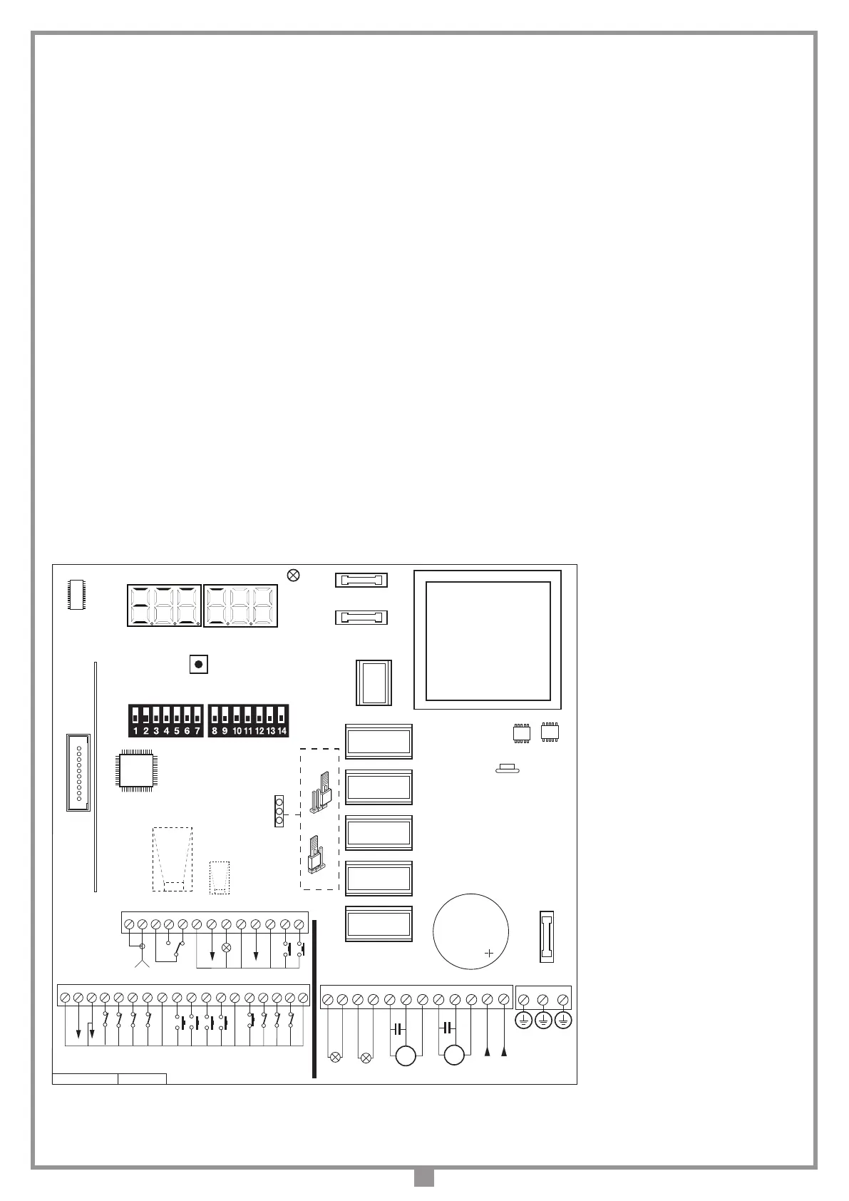
Terminal board connections
1 Outer conductor for radio receiver antenna.
2 Inner conductor for radio receiver antenna (if an external antenna is tted use
a coaxial type cable RG58 with an impedance of 50Ω)
3 CMN per CH2
4-5 CH2 Potential free N.O. contact requires separate power supply Vmax = 30
Vac/dc: Imax = 1A
6 CMN common for all inputs and outputs
7 24 Vdc controlled output, powering external loads
(1)
8 LS output for an indicator light 24 Vac 3W
9 CMN common for all inputs and outputs
10 ELS electric lock output 12 Vac – 15 W
11 CMN common for all inputs and outputs
12 EMRG1 (NO contact) emergency manoeuvring button input 1
13 EMRG2 (NO contact) emergency manoeuvring button input 2
14 CMN common for all inputs and outputs
15 24 Vdc output, powering external loads
(
(1)
16 CMN common for all inputs and outputs
17 FCC1 (N.C.) gate 1 closing travel limit input
18 FCA1 (N.C.) gate 1 opening travel limit input
19 FCC2 (N.C.) gate 2 closing travel limit input
20 FCA2 (N.C.) gate 2 opening travel limit input
21 CMN common for all inputs and outputs
22 TAL (NO contact) limited opening button input
23 TA (NO contact) opening button input
24 TC (NO contact) closing button input
25 TD (NO contact) dynamic button input
26 CMN common for all inputs and outputs
27 TB (N.C./8.2 kΩ) stop button input (The opening of this contact interrupts the
cycle until a new movement command is given)
(2)
28 CSP (N.C./8.2 kΩ) safety edge input. Opening this contact will provoke a travel
direction inversion during the closing stage and during the opening stage
(2)
29 FTCS (N.C./8.2 kΩ) The opening of this contact will block all movement, until
the obstruction has been removed and the pause time has elapsed, due to
the safety device cutting in, the door will then continue moving in the closing
direction (only with automatic reclosing enabled)
(2)
30 FTCI (N.C./8.2 kΩ) safety and control devices in input (photocells invert
the travel direction when an obstruction is detected). Opening this contact
will provoke a travel direction inversion during closure due to the cutting
in of the safety device
(2)
31 CMN common for all inputs and outputs
32-33 230Vac 40W courtesy light output
34-35 230Vac 40W warning light output (intermittent or continuous activation)
36-37-38 Motor M2 in output Opening- Closing- Common
39-40-41 Motor M1 in output Opening- Closing- Common
42-43 Electronic programmer power supply 230Vac 50/60Hz
44 Electronic programmer earth wire 230Vac 50/60Hz
45 Earth connection
46 Earth connection
Note
(1)
The total of the 2 external device outputs must not exceed 10 W.
Note
(2)
The selection of the type of contact (
N.C./8.2 kΩ) is carried out using parameter
"SC" on the six-gure display.
ALL UNUSED NC CONTACTS MUST BE JUMPED and consequently
the security device test must also be deactivated (FTCI , FTCS - Dip 9 and
Dip 10 "OFF").
If you want to activate the FTCI, FTCS test both the transmission and receiver
parts of the security devices must be connected to the binding post marked
"CTRL 24 Vdc". If the test is active there will be a 1 second delay between
the command transmission and movement of the gate/s.
Switch on the power and make sure that the indicator LEDs are in the fol-
lowing condition.
- L1 Power on ON
- L2 Indicator for the blocking button "TB" ON
(3)
- L3 Indicator for the inverting photoelectric cells "FTCI" ON
(3)
- L4 Indicator for the stop photoelectric cells "FTCS" ON
(3)
- L5 Indicator for the safety edge "CSP" ON
(3)
- L6 Indicator for the opening button "TA" OFF
- L7 Indicator for the opening button "TC" OFF
- L8 Indicator for the limited opening button "TAL" OFF
- L9 Indicator for the sequential command "TD/CH1" OFF
L7
L6
L4
L3
L8L5L2
P1
L9
D1
L1
M2
OPEN
C.
CLOSE
CMN
F1
CS1484A
DC0562
32 33
35 36 37 38
39 40 41
42 43
34
44 45 46
F2
R1
PROG
LC 230V~
L
N
230V~
16 17 19 20 21 22 23 24 251814 15
TAL
TA
TB
FTCI
TD
NC NC NC NC
26 27
TC
NC
M1
OPEN
C.
CLOSE
CMN
LP 230V~
F3
ON
DS1
J1
3 4 6 7 8 9 10 11 1251 2
CMN
EMRG 2
OUT CH2
13
NO
EMRG 1
NO
CMN
ELS
12Vac
CMN
LS
CTRL
24Vac
28 29 30 31
CMN
FTCS
CSP
CMN
NCNCNCNO NONONO
CMN
FCA2
FCC2
FCA1
FCC1
24Vac
CMN
CMN
NO NO
NO
AUX
Programmatore a microcontrollore per 1-2 motori
PRG230M2
18-03-2016
DC0562
Description :
Product Code :
Date :
Drawing number :
P.J.Heath
CARDIN ELETTRONICA S.p.A - 31020 San Vendemiano (TV) Italy - via Raffaello, 36 Tel: 0438/401818 Fax: 0438/401831
Draft :
All rights reserved. Unauthorised copying or use of the information contained in this document is punishable by law
PRG230M2
POS. 1
POS. 2
D1
Six-segment LED display
DS1
Selection dip-switch
F1 1A fuse (delayed 24V
circuit protection
)
F2 4A fuse (delayed 230V
circuit protection
) )
F3 1,6A fuse (delayed
electric lock protection
)
J1 EMRG selection jumper (On/Off)
P1 Programming button (PROG)
R1
Standard radio receiver interface
Note
(3)
Check that the activation of the safety
devices switches the corresponding LEDs off.
If the green power on LED "L1" doesn't light
up check the condition of the fuses and the
power cable connection.
If one or more of the safety LEDs do not
light up check the contacts of the relative
security devices and check that the unused
safety device contacts have been bridged.
 Loading...