Confirm or change settings of the tankless water heater by
choosing one of the two options below.
Parameter Seƫngs Table
A
B
To adjust the parameters:
1. Press the “A” button for 1 second.
2. Use the up or down button on the integrated controller to
select a setting number (See Parameter Settings Table
below).
3. Once the desired setting number is selected, use the “On/
O” button on the controller to change the selection for
the setting number.
Example: Display will change from 01A to 01b for
Maximum Temperature setting.
4. To exit the parameters, press the “A” button on the PC
board for 1 second.
3
PARAMETER SETTINGS
SETTING
#
Option 1: (Recommended)
Using a Bluetooth®-Capable
Smart Device
BEFORE PROCEEDING
Read the Installation and Operation Manual
before you proceed.
• Use the Installation Checklist in the Installation and
Operation Manual after completing the installation.
• Refer to the “Water Quality Guidelines” section in the
manual for important water quality information.
• Pay close attention when unpacking the water heater
carton box as the packing includes additional
components.
• Confirm all included parts are located inside the water
heater carton box (refer to the water heater manual
for a full list of parts).
INITIAL SETTINGS
RECIRCULATION PUMP
RXP199i, RXP160i, CXP199i and CXP160i Models Only
Select the appropriate recirculation mode (Dedicated
or crossover) in the parameter settings.
Dedicated mode (parameter setting 04b):
Crossover mode (parameter setting 04c):
Install crossover valve at the furthest fixture from the
tankless water heater.
NOTE: To remove air,
open a hot water fixture
during pump operation. If
the air is not fully removed,
the pump could run dry.
H
HOT
COLD
C
Pipe Diameter 3/4 in. 1/2 in.
Total 400 ft 100 ft
Maximum Pipe Length (Crossover and Dedicated Mode)
TYPICAL INSTALL
VENTING
• Ensure vent pipe slopes 1/4” per ft. (21 mm per meter)
toward the water heater.
• Ensure vent system doesn't exceed maximum length
allowed.
• Room air installations: Remove the air inlet cap and
install elbow and vent screen (see below).
The end of the
condensate
drain should be
open to
atmosphere.
AIR
GAP
DO NOT submerge end
of pipe in water.
DO NOT install an external
condensate trap.
Refer to the Installation and Operation Manual for
complete details on the above information.
Install Elbow and Vent Screen
Elbow
Vent Screen
Air Inlet Cap
Remove Air Inlet Cap
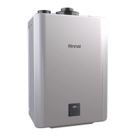
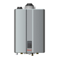
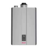
Example Internal
(Indoor) Unit
1
A
B
Refer to manual for additional details.
CONDENSATE
2
SELECTION
# DESCRIPTION
A
b
C
d
01
Maximum Set
Temperature
Residential:
120°F (49°C)
Commercial:
140°F (60°C)
Residential:
140°F (60°C)
Commercial:
185°F (85°C)
02
High Altitude
(Installation
Location)
0 - 2,000 ft
(0 - 610 m)
2,001 -
5,400 ft
(610 -
1,646 m)
5,401 -
7,700 ft
(1,646 -
2,347 m)
7,701 -
10,200 ft
(2,347 -
3,109 m)
03
Service Soon Disabled 0.5 Year 1 Year 2 Years
04
Recirculation
Settings
No
Recirculation
Recirculation
(Dedicated)
Recirculation
(Crossover)
05
Recirculation
Mode
Economy Comfort Commercial
06
Control Switch BMS
Air Handler
(AH)
07
Units in Standby
(EZConnect
TM
)
2 1
08
EZConnect
TM
/
Cascade
Secondary Primary
09
Units in Standby
(Cascade)
1 2 3 4
10
Gas Type NG LPG
12
Built-in
Pump Setting
Without
Pump
With
Pump
13
Water Heater
Model (Factory
Set Values. Not
Adjustable)
199
(3237)
180
(2934)
160
(2530)
130
(2024)
14
Indoor/Outdoor
Internal
(Indoor)
External
(Outdoor)
15
Low
Activation Mode
On O
16
Pump Speed Max High Medium Low
17
First Day Pump
Operation
O On
18
Smart-Circ with
BLE Button
Smart-Circ is
Disabled
Smart-Circ is
Enabled
SETTING
E
5
F
6
If converting from NG to
LPG, apply the supplied
gas conversion label at
an open space above
the existing label on the
left side of the water
heater.
ATTENTION: INSTALLING PERSONNEL
KEY POINTS FOR A SUCCESSFUL INSTALLATION
100000850
7/2023
U362-0878(01)
(For Indoor Installations Only)
Option 2: Using Integrated Controller
GAS CONVERSION
Gas
Conversion
Label
Left Side of
Water Heater
01A
The Bluetooth® word mark and logos are registered trademarks owned
by Bluetooth SIG, Inc.
1. Supply power to the tankless water heater.
2. Display shows “SEt” and Priority button LED is
blinking.
3. Download and install the Rinnai Central™ app.
4. Open the Rinnai Central™ app from your smart device.
Create an account and log in.
5. Push the Bluetooth button on the controller. The
Bluetooth LED light turns solid.
6. Tap "Connect to a Rinnai Tankless Water Heater" on
the Rinnai Central™ app.
7. Follow the steps in the Rinnai Central™ app to confirm
and/or change your tankless water heater settings.
8. Display will turn o.
9. Tankless water heater setup is complete. Press the
on/o button to turn on the tankless water heater.
1. Supply power to the tankless water heater.
2. Display shows “SEt” and Priority button LED is
blinking.
3. Press the Priority button.
4. Display shows “nG” ( Natural Gas).
5. Toggle between gas types “nG”(Natural Gas) or
“LPG” (Liquid Propane Gas) by pressing the up or
down arrow buttons.
6. Select desired gas type to display.
7. Confirm selection of gas type by pressing the On/O
button.
8. Display shows “In” (indoor Installation).
9. Toggle between “In” (indoor) and “ Out” (outdoor) by
pressing the up or down arrow buttons.
10. Select desired location to display (“In” or “ Out”).
11. Confirm installation location by pressing On/O
button.
12. Display flashes desired selections for gas type and
location. Priority button LED also flashing.
13. To restart the selection process, press up arrow
button or press Priority button to confirm gas and
location selections.
14. Display will briefly show “888”and sound a beep.
15. Display will turn o.
16. Initial settings are complete. Press the on/o button to
turn on the tankless water heater.
Priority
button and
LED
Bluetooth
button and LED
Up and Down
arrows
On/O
button
See Installation and Operation Manual for
complete description of each controller button.