BOW/EDGE
OUTPUT jack
RD plug
RDB plug
BELL OUTPUT jack
RD
RDB
CR1
T2
T1
HH
HHC
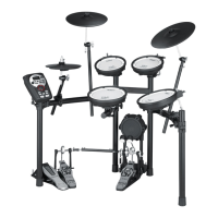
TD-11
KIK
SNR
T3
01
Stand (MDS-4V)
TD-11KV parts
02 03
04 05
1/4” plug (mono)
Stereo
1/4” plug
To AC outlet
Indicator
Amplied speakers, etc.
Stereo
headphones
AC adaptor
* To prevent malfunction and/
or damage to speakers or other
devices, always turn down the
volume, and turn o the power
on all devices before making any
connections.
* After attaching the drum sound
module to the stand, use the
drum key to loosen the sound
module mounting plate, and
adjust the angle of the TD-11.
To prevent the inadvertent
disruption of power to
your unit (should the plug
be pulled out accidentally),
and to avoid applying
undue stress to the DC IN
jack, anchor the power
cord using the cord hook,
as shown in the illustration.
Check the included items
❏ Hi-hat control
pedal (FD-8)
❏ Kick pad (KD-9) ❏ Cymbal pad for
hi-hat (CY-5)
❏ V-Cymbal for crash
(CY-12C)
❏ V-Pad for snare/tom
(PDX-8 x 2)
❏ V-Pad for tom
(PDX-6 x 2)
Assemble the stand Attach the parts
Connect the pads to the drum sound module Connect the AC adaptor and speakers
This completes assembly and connections.
Assembly procedure
Assemble the stand using the procedure described in the MDS-4V Owner’s Manual.
❏ V-Cymbal for ride
(CY-13R)
* Fasten the cables so that they
will not obstruct your playing;
use cable clips at locations
marked
, and cable ties at
locations marked
.
Make sure to wrap the cable
ties around the pipes.
* For reasons of safety, do not spread the
stand wider than 1.0 meters (40 inches).
As seen from the front
1.0 m
The parts required to assemble
the stand (MDS-4V) are listed in
the MDS-4V Owner’s Manual.
Check the owner’s manual and
make sure that you have all of
the parts.
As soon as you open the package, check to see that all items are included. If anything is missing, please contact your dealer.
* Use a commercially available kick pedal.
Cymbal mounts
Pad mounts
Hi-hat mount
Pad mounts
If the stand wobbles, loosen
this hand knob and adjust
the height.
Attach the drum sound
module (TD-11)
Assemble the hi-hat control pedal (FD-8)
Attach the kick pedal (KD-9)
Install the kick pedal
securely.
Tilt it forward slightly.
Attach the snare (PDX-8) and
toms (PDX-8, PDX-6)
Attach the hi-hat (CY-5)
Loosen
Tighten
Rod
PDX-6 PDX-6
PDX-8
KD-9
CY-5
CY-12C
CY-13R
TD-11
FD-8
PDX-8
Position so there is
12–15 cm of space
between the snare and
tom.
The hi-hat should
be placed about
20 cm higher than
the snare.
Place directly
below the hi-hat.
The snare and tom
3 should be at the
same height.
01
■ KD-9 (Kick)
02
Position the beater so that it strikes
the center of the head, then secure the
kick pedal and KD-9 rmly in place.
NOTE
* Install the kick pedal securely.
* Take care not to pinch your ngers.
* Depending on how you’re using the unit,
the bolts that attach the pedal to the plate
could become loose, causing the pedal to
rattle during performance.
In such cases, use commercially available
tools to tighten the bolts.
Adjusting the Anchor Bolts.
When using the kick pedal on a carpet or on a
drum mat (TDM series), the slip-prevention tape
that’s on the base should prevent the KD-9 from
moving around.
However, if that’s not enough to keep the KD-9
in a xed position, you can adjust things so that
the tips of the anchor bolts protrude through the
base. That should keep it in place and make it
easier for you to play.
When Using a Twin Pedal
Position the two beaters equally apart from the center of the pad as
shown in the gure at left. If one of the beater is further away from
the center than the other, the sound from the further beater will be
lower in volume, or will not sound as desired.
Using a twin pedal will result in lower sensitivity as compared to when
a single pedal is used. Raise the sensitivity on the sound module.
For details, see “Setting the Pad Sensitivity [F2] (BASIC)” in the owner’s
manual.
NOTE
* When used on ooring, the anchor bolts
may damage the oor. Adjust the anchor
bolts correctly.
* The tips of the anchor bolts are sharp.
Handle with care
Detailed explanation of each part
Component names
* Use a commercially available kick pedal.
Other side
Attach the kick pedal.
Beater
Install the kick pedal
securely.
03
Step on the kick pedal and make sure that it’s properly attached and in a stable position.
Check to make sure that the base of the KD-9 and the kick pedal both make
contact with the oor.
Output jack
Head
Anchor bolts
Base
Mounting plate for the kick pedal
Slip-prevention tape
When using on the carpet or
drum mat
When using on
the oor
Position things so the strik-
ing surface of the kick drum
is approximately 10–12 cm
in front of the pipe.
Tilt it downward
slightly, so the stick
doesn’t contact the
rim.
❏ Drum sound module
(TD-11)
❏ Connection cable
(special for TD-11)
❏ AC adaptor
Manual set
❏ Setup Guide (this document)
❏ TD-11 Owner’s Manual
* Use the drum key included with the MDS-4V to assemble the parts and make adjustments.
Setup Guide
Connection procedure
* Insert the plug
rmly, making sure
it’s all the way in.
1. Connect the cable to the
TD-11 as shown in the
illustration.
Insert the connector all the
way, then turn the knobs
to fasten it securely.
2. Labels indicating the pad to
be connected are attached
to the cable.
Connect the cable to the
OUTPUT jack of each pad as
shown in the illustration.
Knob
Attach the crash cymbal (CY-12C) and ride cymbal (CY-13R )
Allow for 10–12 cm
of space between
tom 1 and tom 2.
Upper clutch
Clutch felt
(small)
Clutch felt
(large)
Lower clutch
Align with indentation
While pressing
Use Drum Key to
tighten
Bolt
Copyright © 2012 ROLAND CORPORATION
All rights reserved. No part of this publication may be reproduced in any form without the written permission of ROLAND CORPORATION.
Before using this unit, carefully read the sections entitled: “USING THE UNIT SAFELY” and “IMPORTANT NOTES.”
These sections provide important information concerning the proper operation of the unit. Additionally, in order
to feel assured that you have gained a good grasp of every feature provided by your new unit, Setup Guide and
Owner’s Manuals should be read in its entirety. The setup guide and manuals should be saved and kept on hand
as a convenient reference.
* A variety of commercially available beaters
can be used, including felt, plastic, or
wood types.
However if a felt beater is used, the felt
may leave marks on the striking surface.
When you’ve nished making connections, turn on the power as described
in the TD-11 Owner’s Manual, and verify that you can hear sound.
Loosen with the drum key,
and tighten after adjusting
Deeper
Shallower
Slide the arm
Adjusting the pedal depth
Anchor bolt
Attach the anchor bolt
(if installing on a drum mat)
Anchor bolt
Spring for the
anchor bolt
* The tip of the mount is sharp. Handle it with care.
* When setting up or storing the stand, be careful not to pinch the ngers you use to
handle the stand.
Check to be sure they’re making contact with the oor
Bolt
Base
Attach the stopper so that
the bolt is on the right-hand
side, from the performer’s
perspective.
Tighten the wing nut to obtain an appropriate
amount of sway.
Tighten the bolt with a drum key.
Stopper
Wing nut
Felt washer
“Roland” logo on the farther side
Place at a slightly
lower position than
the crash symbol.