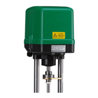
Einbau- und Betriebsanleitung
Installation and Operating instructions
Instructions de montage et de service
Potentiometer für ST 5112
Potentiometer for ST 5112
Potentiomètre pour ST 5112
5112-8510
Baureihe / Series / Séries
Potentiometer
07/2009
1. Montage Potentiometer:
Die Potentiometer sind mit Hebel, Stellring,
Ritzel, Litze und Leiterplatte jeweils für
rechtsseitigen (POT 1) und linksseitigen
(POT 2) Anbau vormontiert.
Das erste Potentiometer POT 1 wird immer
auf der rechten Seite montiert (mit Blick auf
die Enschalterführung). Die zugehörige Lei-
terplatte (16) kommt in die untere Position.
Ein eventuell benötigtes zusätzliches Poten-
tiometer POT 2 ist links zu montieren, die
zugehörige Leiter-platte (29) in der oberen
Position.
1. Mounting of the potentiometer:
The potentiometers are pre-assembled with a
lever, adjustable ring, pinion, cord and circuit
board for mounting on the right-hand side
(POT 1) and on the left-hand side (POT 2).
The first potentiometer (POT 1) is always
mounted on the right-hand side (facing the
terminal switch guide). The associated circuit
board (16) is inserted into the lower position.
Any additional potentiometer required (POT
2) must be mounted on the left-hand side
and its associated circuit board (29) in the
upper position.
1. Montage du potentiomètre:
Les potentiomètres sont équipés préalable-
ment de levier, anneau ajustable, pignon,
cordon et de carte de circuits imprimés, pour
le montage au côté droit (POT 1) et pour le
montage au côté gauche (POT 2).
Le premier potentiomètre POT 1 est toujours
monté au côté droit (avec vue sur le guidage
du commutateur de fin de course). La carte
de circuits imprimés correspondante (16) est
montée dans la position inférieure.
Un potentiomètre supplémentaire éventuel-
lement nécessité POT 2 est à monter à
gauche, la carte de circuits imprimés corres-
pondante (29) dans la position supérieure.
POT 2
POT 1
16
29
Zuordnung Zähnezahl / Hub Anschlußplan Potentiometer:
Assignment number of teeth / stroke Potentiometer connection diagram:
Assignation nombre de dents / course Diagramme des connexions du potentiomètre:
Hub [mm] Zähnezahl
[Z]
15 16
20 18
25 22
35 30
40 36
41 42 43
100%
0%
M
POT 1 POT 2
M
44 45
%0
100%
46
gelb
grau
rot
gelb
grau
rot

 Loading...