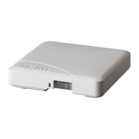
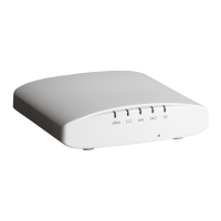
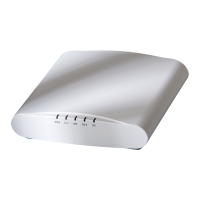
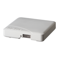
R730 Access Point
Quick Setup Guide
This Quick Setup Guide provides step-by-step instructions on
how to install and begin using your Ruckus R730 Dual-Band
802.11ax Multimedia Wi-Fi Access Point (AP). After completing
the steps described in this guide, you will be able to place the
R730 at your site and begin providing wireless access to users.
NOTE: R730 is supported in these SmartZone releases: 3.6.2,
5.1.1.
R730 is supported in these ZoneDirecor releases: 10.1.2, 10.3.
NOTE: R730 is not supported in SmartZone release 5.0,
SmartZone 5.1 or ZoneDirector 10.2. Customers with R730 APs
will not be able to upgrade to SmartZone 5.0, SmartZone 5.1
or ZoneDirector 10.2.
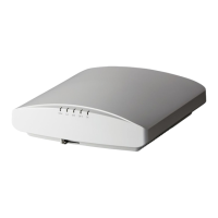
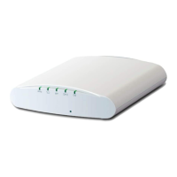
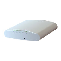
FIGURE 1 R730 - top
This Guide in Other Languages
• 请从以下网站获得该指南的简体中文版 https://
support.ruckuswireless.com.
• Vous trouverez la version française de ce guide à l'adresse
suivante https://support.ruckuswireless.com.
• このガイドの日本語版は https://support.ruckuswireless.com で
ご覧ください。
• 이 가이드의 한국어 버전은 웹 사이트 (https://
support.ruckuswireless.com) 에서 확인하시기 바랍니다.
• Veja a versão em português (Brasil) deste guia em https://
support.ruckuswireless.com.
• Puede ver la versión en español (América Latina) de esta guía
en https://support.ruckuswireless.com.
Before You Begin
Before deploying Ruckus products, please check for the latest
software and the release documentation.
• Release Notes and other user documentation are available at
http://support.ruckuswireless.com/documents.
• Software upgrades are available at http://
support.ruckuswireless.com/software.
• Software license and limited warranty information are
available at http://support.ruckuswireless.com/warranty.
Package Contents
A complete R730 installation package includes all of the items
listed below:
• R730 Access Point
• One wall-mount anchor kit, including two 1" No. 8 steel pan
head Phillips sheet metal screws and wall-mount anchors
• One external T-bar bracket (two unassembled parts)
• Service Level Agreement/Limited Warranty Statement
• Declaration of Conformity
• Regulatory Statement
• Ruckus Access Point Getting Started Guide
• AP Cloud Management Insert
• This Quick Setup Guide
Step 1: Collecting Setup Requirements,
Hardware and Tools
• Admin PC (computer with an Ethernet port and Wi-Fi adapter)
• Cat 5e (or better) Ethernet cable
• Ruckus Wireless 48VDC power adapter (sold separately) --OR--
• 802.3at-compliant Power over Ethernet (PoE) switch or PoE
injector
NOTE: The PoE switch port must run link layer discovery
protocol (LLDP) power over Ethernet/MDI (PoE+) in order for
the R730 to operate in full-power mode. This may require
enabling both LLDP and Power via MDI (dot3) on the switch,
if available.
NOTE: If powered by 802.3at PoE, note that the feature set
is reduced, as follows:
– 4x4 (2.4GHz) + 4x4 (5GHz) chain operation mode (reduced
from 4x4 (2.4GHz) + 8x8 (5GHz) under full power)
– LAN1 (10/100/1000 Mbps Ethernet port is disabled)
NOTE: The recommended PoE injector for the R730 is
GRT-480125A (60W power rating and 1 Gbps link speed). If
using the recommended PoE injector, you must 1) manually
select AT+ mode as the power mode in the SmartZone/
ZoneDirector GUI, and 2) force 1Gbps link speed on the
switch.
Optional hardware and tools:
• Customer-supplied small padlock with a 3.5mm (0.14”) or
smaller shackle diameter, used to fasten the AP to the secure
mounting bracket or the T-bar bracket.
• Customer-ordered Ruckus Wireless 902-0120-0000 secure
mounting bracket kit:
– If you are mounting the AP on a at surface using the secure
mounting bracket kit, then you need an electric drill with
4.75mm (3/16”) drill bits.
– If you are mounting the AP on a pipe or pole using the
secure mounting bracket kit, then you will also need a
38.1mm to 63.5mm (1.5" to 2.5") pipe or pole, two pole
clamps, and hand tools to tighten the clamps.
Step 2: Connecting Your Computer to the
AP
1. Using an Ethernet cable, connect your computer’s network
port to the 5G ETH PoE port on the AP (1 in the Figure
below).
2. Using a DC power adapter (sold separately), connect the AP's
48V DC port (2 in the Figure below) to a convenient and
protected power source.
NOTE: Alternatively, connect the 5G ETH PoE port to a PoE
injector or switch for both power and network
connectivity.
FIGURE 2 AP Ports
TABLE 1 R730 bottom panel elements
No. Label Description
1 5G ETH
PoE
100/1000/5000 Mbps PoE In Port:
RJ-45 Ethernet port (supports
802.3at/at+ PoE in)
2 1G ETH 10/100/1000 Mbps port: RJ-45
Ethernet port (non-PoE)
3 48V
0.75A
48V DC input
4 USB USB Port
• Max Dimensions: 6cm x 2cm x
1.1 cm
• Interface: USB 2.0
• Connector: USB – Type-A plug
3. Verify that the PWR LED on the AP is a steady green.
Copyright
©
2019 CommScope, Inc. All rights reserved. Page 1 of 4
Published November 2019, Part Number 800-71616-001 Rev C