advisable to install the Meter in the distribution board as the
appliance is neither waterproof nor dustproof.
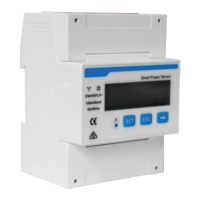
2.2.3
CTs connection
Connect outputs of three current transformers to six inputs of
Meter (CT Current Input), matching terminals white I* and
blue I of CTs with IA* and IA, IB* and IB and IC* and IC inputs
as in the figure below.
Then, close and ensure the three CTs to respective phases
of power connection.
Check that the arrow printed on the CTs indicate the direction
of the load. It is advisable to install the CTs in the distribution
board as the appliance are neither waterproof nor dustproof.
Notes: dimensions in millimeters
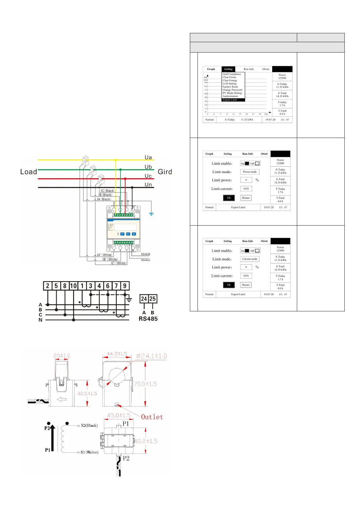
2.2.4
Inverter Configuration
Note: 1. Power mode and current mode could be alternatively
selected;
2.When the setting is completed, the export limitation system
will begin to run.
Chapter 3 - Verifying informations
3.1 Meter Information
Information such as voltage, current, frequency, power, power
factor, baud- rate, communication address and active power
can be displayed in rotation on the display or manually
scrolling by pressing the “→” button on the Meter.