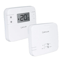
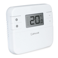
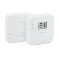
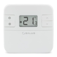
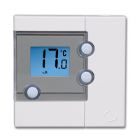
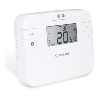
RT310
Thermostat
Introduction
RT310 / RT310TX / RT310RF is a digital room thermosat used to control room temperature. Device
launching heating system by shorting terminal blocks, simultaneously informing the action and
showing this information on the LCD display. Before use please read this manual carefully. Use only
AA 1.5 V alkaline batteries in the thermostat. Place the batteries into the battery slot located under the
cover. Do not use rechargeable batteries.
Product compliance
This product complies with the essential requirements and other relevant provisions of the following EU Directives:
EMC 2014/30/EU, LVD 2014/35/EU, RED 2014/53/EU and RoHS 2011/65/EU. Full text of the EU Declaration of
Conformity is available on www.saluslegal.com
Safety Information
Use in accordance to national and EU regulations. Use the device as intended, keeping it in dry condition.
Product for indoor use only. Installation must be carried out by a qualied person in accordance to
national and EU regulations.
Technical specication
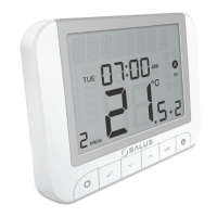
LCD Icon description
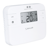
Button functions
RT310 Terminals description
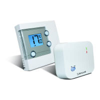
RXRT510 Receiver terminals description
RT310 Wiring diagram
RT310RF Wiring diagram
RT310 RT310TX
Thermostat supply 2 x AA alkaline batteries 2 x AA alkaline batteries
Receiver supply - 230 V AC
Thermostat rating max 3 (1) A -
Receiver rating max - 16 (5) A
Outputs
Voltage free
NO / COM /NC terminals
Voltage free
NO / COM terminals
Temperature range 5 - 35°C 5 - 35°C
Terminal Description
1 - COM Common Terminal
2 - NC Switched Live OFF
3 - NO Switched Live ON
Terminal Description
NO Switch Terminal
COM Common Switch Terminal
L, N Supply (230 V AC)
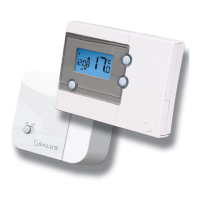
RT310 / RT310TX Thermostat RXRT510 Receiver
1
5
6
7
8
3
2 4
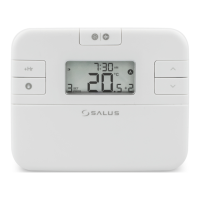
1. Turn on the LCD backlight
2. Turn On/O the Frost Mode
3. Increase button
4. Decrease button
1. Heating Mode ON
2. Frost Protection Mode ON
3. RF signal indicator (only in RT310RF)
4. Low battery status
5. Temperature unit
6. Room / setpoint temperature
5. When in Manual Mode,
ON will turn the boiler on.
6. When in Manual Mode,
OFF will turn the boiler o.
7. Receiver operates in automatic mode
according to the thermostat
8. Receiver output is controlled
by the On/O slide switch.
1 5
6
3
2
4
NO COM L N
DIP Switch Settings
Note: If you are using the RT310RF pack, the pairing between the thermostat and the receiver
is already done.
RT310, RT310TX, RT310RF
The DIP Switches can be found on the rear of your thermostat.
Control feature TPI Span
Operation When TPI is selected on DIP
switch № 2, the DIP switch №
1 is functional. You can choose
the Cycles Per Hour between
a lower comfort level (6CPH)
and a higher comfort level
(9CPH).
When Span is selected
on DIP switch № 2,
the DIP switch № 1 is
not functional. The
temperature accuracy of
your thermostat is set to
± 0.25 °C.
868.0-868.6MHz; <13dBm
Quick Guide