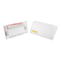
Wiring Centre
Model No:- TC100
Instruction Manual
2 Port Motorised Valve System (S - Plan)
HW Motorised Valve
Model No. MV222
HWS
(NO)
HWC
(NC)
Cylinder Thermostat
Model No. CT100
N
LSL
11 12
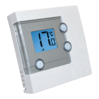
Room Thermostat
Model Nos RT200
RT300
AC
Mains IN
protected
by 5amp
fuse
1
ENL
N E
Boiler
N
N
N
N
L
NLSL
N
NL 2
1
34
E
N
E
E
E
E
NB. Neutral not required
on RT300 & RT500
1
15
C
E
RT500
E
14
2
2 345 6789101112131415 16
Optional Frost
Thermostat
Model No. FT100
CH Motorised Valve
Model Nos. MV222
MV228
Yellow/Green
Blue (N)
Brown (L)
Orange CH Call (C)
Grey CH (N0)
E
N
4
6
7
N E
NL
Pump
E
Programmer
Model No. EP200
7
6
8
E
N
Brown (L)
Orange CH Call (C)
Grey HW (N0)
Yellow/Green
Blue (N)
11 10 9
13
12
3 2
Wiring centres are designed to simplify wiring and circuit checking. The TC100 does this with an easy
to understand manual suited to all popular central heating and hot water systems. Adequate wiring
space, large terminals, cable access points and cable clamps add to the simplicity of the TC100.
Note: links shown on diagram should be made by the installer.
For ‘S Plan’ link
2 - 4
7 - 11
8 - 14
2 X 2 PORT MOTORISED VALVE SYSTEM (S PLAN)
EP200
RT200
CT100
EP200
RT200
The TC100 Wiring Guide assumes that the Installer can identify from
the boiler, pump and controls literature to hand, the mains supply
and switch terminals.
WIRING CENTRE TC100
Note
Links shown
Should be made
by the installer