Note: Use the rear plate of the VS35 thermostat only with this model.
Note: In the KL06 wiring centre, the SL terminal is marked with an arrow
icon .
Installation Manual
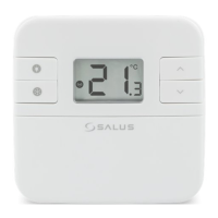
Wired thermostat with digital display for the control
of temperature in UFH & RAD systems
Model: VS35W (white), VS35B (black)
Introduction
The VS35 thermostat controls temperatures of individual heating zone
in underoor heating systems. Thermostat allows for signicant savings
thanks to the possibility of maximum reduction the set temperature.
The full version of the manual in PDF format is available on the website
www.salus-controls.eu
Introduction
This product complies with the following EU Directives: Electromagnetic
Compatibility 2014/30/EU, Low Voltage Directive 2014/35/EU and RoHS
2011/65/EU. Full information is available on the website www.saluslegal.com
Safety Information
Use in accordance with national and EU regulations. Use the device only as
intended, keeping it in a dry condition. The product is for indoor use only.
Installation must be carried out by a qualied person in accordance with
national and EU regulations.
Terminals description
Terminal Description
L,N Power Supply 230 V AC
NSB Night SetBack (input 230 V AC)
SL Switched output (230 V AC)
S1, S2 External temperature sensor
Proper thermostat placement
LCD Icon description Wiring diagrams
Installation
M
M
150 cm
min 20 cm
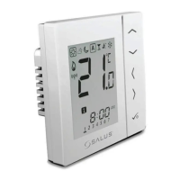
Button
Function
Increasing / decreasing temperature or value
Selection of the operating mode, switching between values
Short press - selection conrmation
Long press - entry to or exit from the menu
Long press causes blocking or unlocking the thermostat
+
Button Functions
2 3 4 5 6
7
8
9
10
11
12
13
14
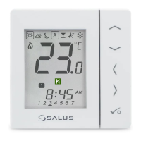
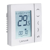
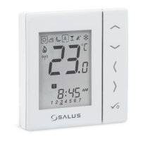
1
1. Current active mode
2. Comfort mode
3. Standard mode
4. Economic mode
5. Automatic mode
6. Frost protection mode
7. Temperature unit
8. Manual mode / temp. override
9. Current / set temperature
10. Key lock
11. Settings
12. Additional temperature sensor
13. Cooling
14. Heating
Importer:
SALUS Controls plc
Salus House
Dodworth Business Park
Whinby Road,
Barnsley S75 3SP,
United Kingdom
DISTRIBUTOR
OF SALUS CONTROLS:
QL CONTROLS Sp. z o.o., Sp. k.
Rolna 4,
43-262 Kobielice,
Poland
www.salus-controls.eu
SALUS Controls is a member of the Computime Group
Maintaining a policy of continuous product development SALUS Controls plc reserve the right to
change specification, design and materials of products listed in this brochure without prior notice.
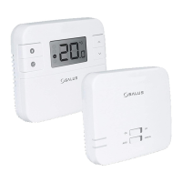
VS35 thermostat in connection with actuator or pump
OR
VS30 thermostat in connection with a boiler with a “NO” voltage free
terminal through the RM-16A relay
VS35 thermostat in connection with wiring centre
VS35
L
L
N
N
L
N
SL
SL
S1 S2
NSB
INPUT
T
L
N
SL
KL08NSB
KL06
VS30
L NSLS1 S2
NSB
OUTPUT
T
L
N
AC 230V
In this diagram, the VS30 thermostat manages the NSB function,
more details about NSB function can be found on the next page.
NSB function and an additional temperature sensor is optional.
The VS35 thermostat has been designed for ush mounting in
a standard electrical box with a diameter of 60 mm.
L